Wiring diagrams
A module on Arduino or ESP32: the diagram, wires by pin, current draw and example code. Each diagram opens in the builder so you can change it.
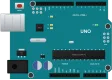
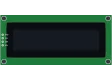
How to connect an LCD1602 to Arduino over I2C
Four wires, address 0x27 or 0x3F and contrast.
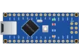
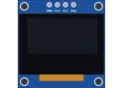
How to connect an OLED SSD1306 to Arduino
0.96″ display on A4 and A5, address 0x3C.
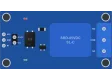
How to connect a relay to Arduino
5 V module on D7, triggered by LOW.
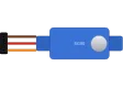
How to connect an SG90 servo to Arduino
Signal on D9, separate 5 V supply, common ground.
How to connect a DHT22 to ESP32
Three wires, data on GPIO4, 3.3 V power.
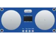
How to connect an HC-SR04 to ESP32
Echo through a 1 kΩ and 2 kΩ divider, 5 V power.
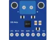
How to connect a MAX98357A to ESP32
I2S on GPIO25, 26 and 27, 4-8 Ω speaker.
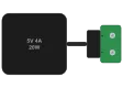
How to connect a WS2812B strip to ESP32
5 V 4 A supply, 74AHCT125 and 330 Ω on DIN.
How the circuits are built
Each circuit is built in the builder from parts of the pinout catalog, and the pins and labels on it are the same as on the boards. The circuit is checked by the same ERC as in the builder: 5 V on 3.3 V pins, current drawn from power pins, common ground, completeness of the I2C, SPI and UART buses. The published circuits have no errors or warnings.
The "Open in builder" link carries the circuit into the editor: there you can change the board, move wires to other pins and immediately see what the check says. From there the circuit can also be moved to a breadboard and into the power calculation.