Board and module pinouts
195 boards and modules. A pin on the diagram shows its functions, limits and where that is known from.
Nothing found. Try a chip name: ESP32, ATmega328, nRF24.
ESP32
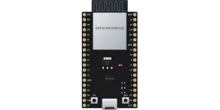
ESP32-DevKitC V4 (ESP32-WROOM-32E), 38 pins
ESP32 (ESP32-D0WD-V3)38 pins
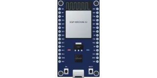
ESP32 DOIT DevKit V1, 30 pins
ESP32 (ESP32-D0WDQ6 / D0WD-V3)30 pins
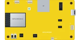
CYD, Cheap Yellow Display (Sunton ESP32-2432S028R, 2,8″)
ESP32 (ESP32-D0WD)14 pinspartly verified
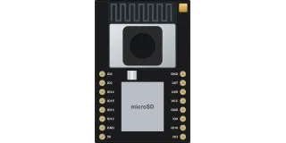
ESP32-CAM (AI-Thinker)
ESP32 (ESP32-D0WDQ6)16 pinspartly verified
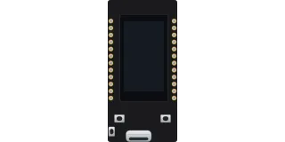
LilyGO T-Display (ESP32, 1,14″ ST7789)
ESP32 (ESP32-D0WDQ6)24 pins
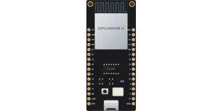
WEMOS LOLIN D32
ESP32 (ESP32-D0WDQ6)32 pins
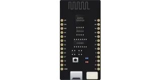
WEMOS LOLIN32 Lite
ESP32 (ESP32-D0WDQ6)26 pins
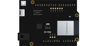
Wemos D1 R32 (ESP32 in the Arduino Uno form factor)
ESP3241 pinspartly verified
ESP32-S2 and S3
ESP32-C and H
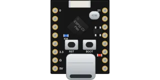
ESP32-C3 SuperMini
ESP32-C316 pins
ESP32-C5-DevKitC-1 v1.2
ESP32-C532 pins
ESP32-C3-DevKitM-1
ESP32-C330 pins
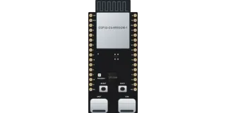
ESP32-C6-DevKitC-1
ESP32-C632 pins
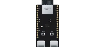
ESP32-H2-DevKitM-1
ESP32-H230 pins
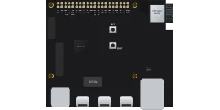
ESP32-P4-Function-EV-Board v1.5.2
ESP32-P440 pins
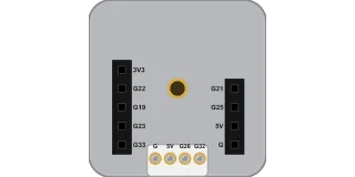
M5Stack ATOM Lite (ESP32-PICO-D4)
ESP32-PICO-D413 pins
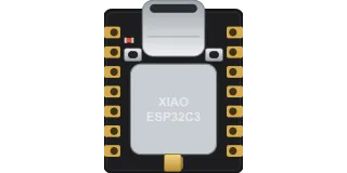
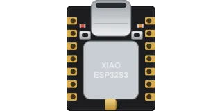
Seeed XIAO ESP32C3
ESP32-C314 pins
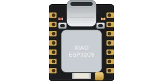
Seeed XIAO ESP32C6
ESP32-C614 pins
ESP8266
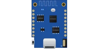
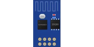
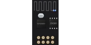
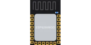
Arduino
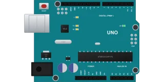
Arduino Uno R3
ATmega328P44 pins
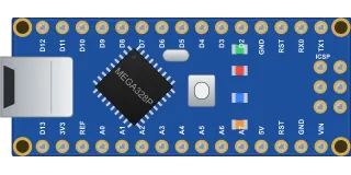
Arduino Nano (ATmega328P)
ATmega328P36 pinspartly verified
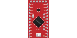
Arduino Pro Mini 5 V / 16 MHz
ATmega328P34 pins
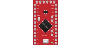
Arduino Pro Mini 3.3 V / 8 MHz
ATmega328P34 pins
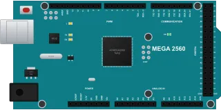
Arduino Mega 2560 R3
ATmega256098 pinspartly verified
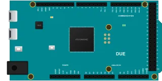
Arduino Due (SAM3X8E)
AT91SAM3X8E92 pins
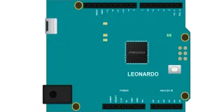
Arduino Leonardo (ATmega32U4)
ATmega32U438 pins
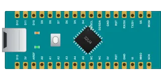
Arduino Micro (ATmega32U4)
ATmega32U434 pins
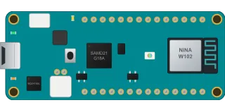
Arduino MKR WiFi 1010 (SAMD21, Wi-Fi)
ATSAMD21G18A30 pins
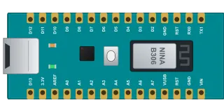
Arduino Nano 33 BLE / BLE Sense (nRF52840)
nRF5284030 pinspartly verified
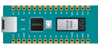
Arduino Nano 33 IoT (SAMD21, Wi-Fi)
ATSAMD21G18A30 pins
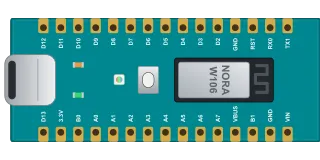
Arduino Nano ESP32 (ESP32-S3)
ESP32-S330 pins
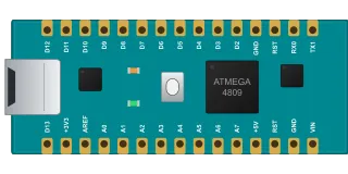
Arduino Nano Every (ATmega4809)
ATmega480930 pins
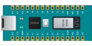
Arduino Nano RP2040 Connect
RP204030 pins
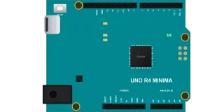
Arduino Uno R4 Minima
RA4M138 pins
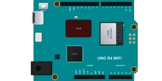
Arduino Uno R4 WiFi
RA4M138 pins
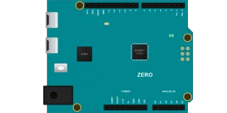
Arduino Zero (ATSAMD21G18)
ATSAMD21G18A38 pins
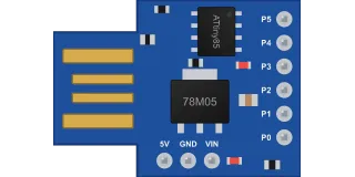
Digispark (ATtiny85, USB-A on the board)
ATtiny859 pins
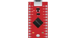
Pro Micro 3.3 V / 8 MHz (ATmega32U4)
ATmega32U424 pins
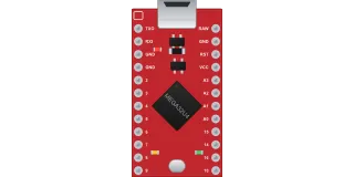
Pro Micro 5 V / 16 MHz (ATmega32U4)
ATmega32U424 pins
Raspberry Pi
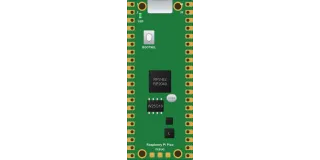
Raspberry Pi Pico
RP204043 pins
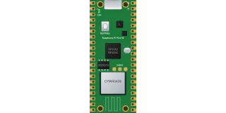
Raspberry Pi Pico W
RP204043 pins
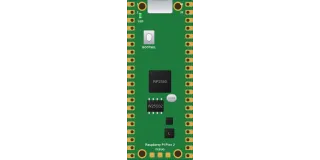
Raspberry Pi Pico 2
RP2350A43 pins
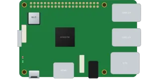
Raspberry Pi 3 Model B+
BCM2837B040 pins
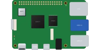
Raspberry Pi 4 Model B
BCM271140 pins
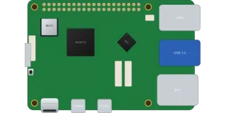
Raspberry Pi 5
BCM271240 pins
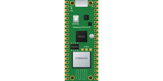
Raspberry Pi Pico 2 W
RP2350A43 pins
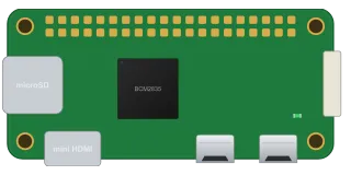
Raspberry Pi Zero
BCM283540 pins
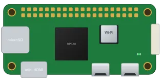
Raspberry Pi Zero 2 W
RP3A0 (BCM2710A1)40 pins
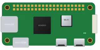
Raspberry Pi Zero W
BCM283540 pins
STM32
Resistors and potentiometers
Capacitors
LEDs
Diodes and Zener diodes
Transistors
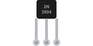
2N3904 transistor (NPN, TO-92)
2N 39043 pins
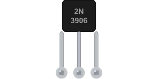
2N3906 transistor (PNP, TO-92)
2N 39063 pins
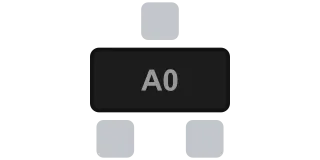
AO3400 MOSFET (N-channel, 30 V, 5.7 A, SOT-23)
AO34003 pins
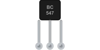
BC547 transistor (NPN, TO-92)
BC 5473 pins
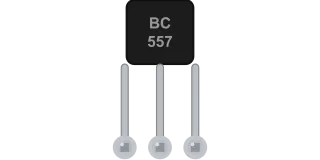
BC557 transistor (PNP, TO-92)
BC 5573 pins
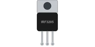
IRF3205 MOSFET (N-channel, 55 V, 110 A, TO-220)
IRF32053 pins
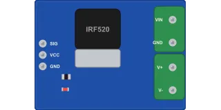
IRF520 MOSFET module (SIG, VCC, GND; VIN, V+, V−)
Vishay IRF5207 pinspartly verified
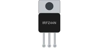
IRFZ44N MOSFET (N-channel, 55 V, 49 A, TO-220)
IRFZ44N3 pins
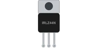
IRLZ44N MOSFET (N-channel, logic level, TO-220)
IRLZ44N3 pins
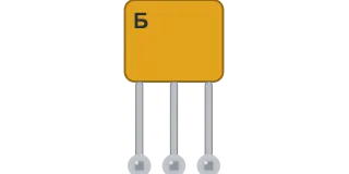
KT315 transistor (NPN, KT-13 package)
KT3153 pinspartly verified
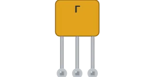
KT361 transistor (PNP, KT-13 package)
KT3613 pinspartly verified
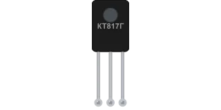
KT817 transistor (n-p-n, 3 A, KT-27 package)
KT8173 pinspartly verified
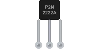
P2N2222A transistor (onsemi, NPN, TO-92, C-B-E)
P2N 2222A3 pins
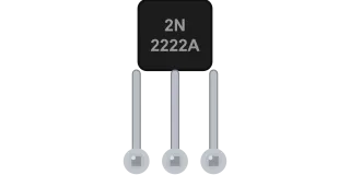
2N2222A / PN2222A transistor (NPN, TO-92, E-B-C)
2N 2222A3 pins
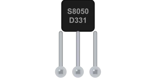
S8050 transistor (NPN, TO-92, E-B-C)
S8050 D3313 pins
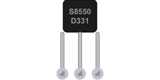
S8550 transistor (PNP, TO-92, E-B-C)
S8550 D3313 pinspartly verified
Buttons and switches
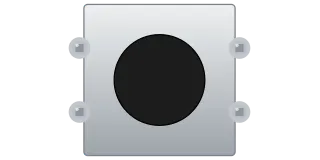
12×12 mm tactile button (4 pins)
12×12 tactile button4 pinspartly verified
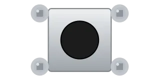
6×6 mm tactile button (4 pins)
6×6 tactile button4 pins
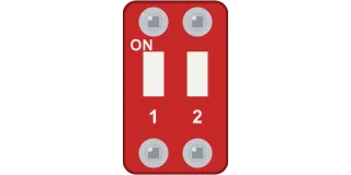
2-position DIP switch
DIP switch 2 pos.4 pinspartly verified
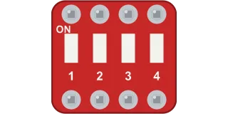
4-position DIP switch
DIP switch 4 pos.8 pinspartly verified
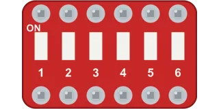
6-position DIP switch
6-position DIP switch12 pinspartly verified
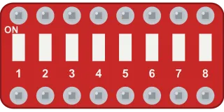
8-position DIP switch
8-position DIP switch16 pinspartly verified
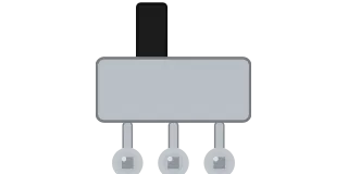
SS-12D00 slide switch (SPDT, 3 pins)
SS-12D003 pins
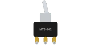
MTS-102 toggle switch (SPDT ON-ON, 3 pins)
MTS-1023 pinspartly verified
Buzzers
ICs
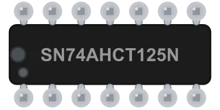
74AHCT125 buffer (DIP-14), 3.3 to 5 V level shifter
SN74AHCT12514 pins
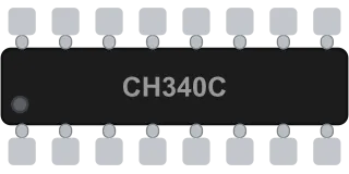
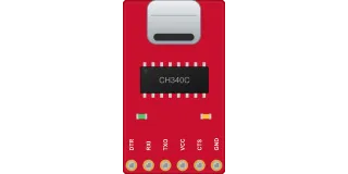
CH340C chip (SOP-16), USB-UART bridge without a crystal
CH340C16 pins
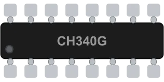
CH340G chip (SOP-16), USB-UART bridge with a crystal
CH340G16 pins
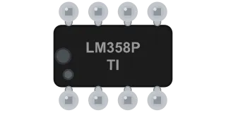
LM358 operational amplifier (DIP-8)
LM3588 pins
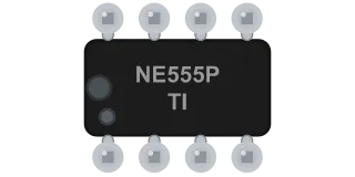
NE555 timer (DIP-8)
NE5558 pins
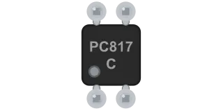
PC817 optocoupler (DIP-4)
PC8174 pins
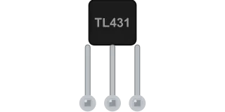
TL431 adjustable shunt regulator (TO-92)
TL4313 pins
Programmers
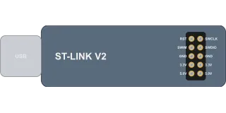
Radio modules
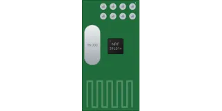
nRF24L01+ (module with an on-board antenna)
nRF24L01+ (Nordic)8 pinspartly verified
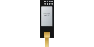
nRF24L01+PA+LNA (with SMA antenna)
nRF24L01+ (Nordic)8 pinspartly verified
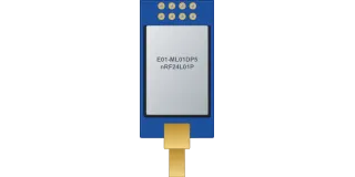
Ebyte E01-ML01DP5 (nRF24L01P, 20 dBm, SMA)
nRF24L01P (Nordic)8 pins
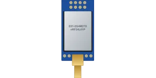
Ebyte E01-2G4M27D (nRF24L01P, 27 dBm, SMA)
nRF24L01P (Nordic)12 pinspartly verified
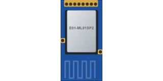
Ebyte E01-ML01SP2 (nRF24L01P, 20 dBm, SMD)
nRF24L01P (Nordic)10 pins
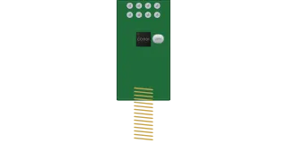
CC1101 green module 2×4 (433 MHz)
CC1101 (TI)8 pinspartly verified
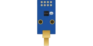
Ebyte E07-M1101D-SMA (CC1101, 433 MHz)
CC1101 (TI)8 pins
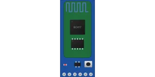
Bluetooth HC-05 on a ZS-040 carrier (6 pins)
CSR BC417 (Bluetooth 2.0 SPP)6 pinspartly verified
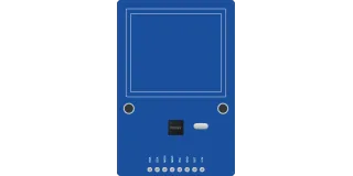
RFID reader RC522 (MFRC522, 13.56 MHz, SPI)
NXP MFRC5228 pinspartly verified
Sensors
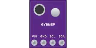
BME280 4 pins (VIN 3.3-5 V, GYBMEP)
Bosch BME2804 pinspartly verified
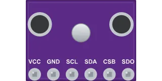
BME280 GY-BME280 (6 pins, 3.3 V only)
Bosch BME2806 pinspartly verified
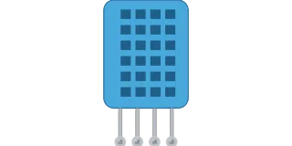
DHT11 humidity and temperature sensor
DHT114 pins
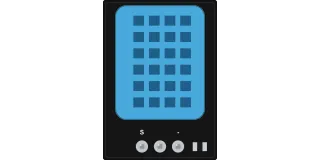
DHT11 module KY-015 (S, +V, −)
DHT113 pinspartly verified
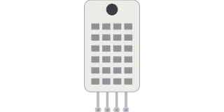
DHT22 humidity and temperature sensor (AM2302)
DHT22 (AM2302)4 pins
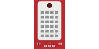
DHT22 (AM2302) module on a board (+, out, −)
DHT22 (AM2302)3 pinspartly verified
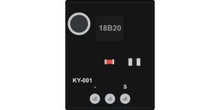
DS18B20 KY-001 module (S, +V, −)
DS18B203 pinspartly verified
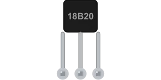
DS18B20 temperature sensor (TO-92)
DS18B203 pins
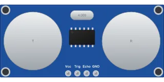
HC-SR04 ultrasonic rangefinder
circuit with 40 kHz ultrasonic transducers4 pinspartly verified
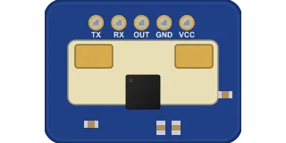
HLK-LD2410C, 24 GHz presence radar (UART and OUT)
24 GHz FMCW radar5 pins
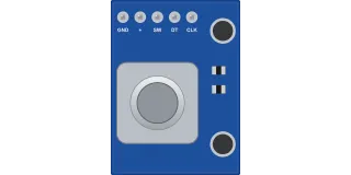
KY-040 encoder (EC11 with button)
EC11 mechanical incremental encoder with button5 pinspartly verified
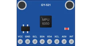
MPU-6050 GY-521 (accelerometer + gyroscope)
InvenSense MPU-60508 pinspartly verified

Bare TCRT5000 reflective optical sensor (4 pins)
Vishay TCRT50004 pins
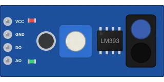
TCRT5000 line and edge sensor with LM393 (4 pins)
Vishay TCRT5000 and LM393 comparator4 pinspartly verified
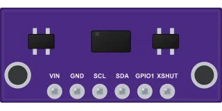
VL53L0X laser distance sensor GY-VL53L0XV2 (6 pins)
ST VL53L0X6 pinspartly verified
Displays and LEDs
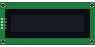
LCD1602 display with an I2C adapter on PCF8574 (0x27 / 0x3F)
HD44780 + PCF8574T4 pinspartly verified
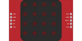
8×8 matrix on MAX7219 (input VCC, GND, DIN, CS, CLK)
Maxim (ADI) MAX721910 pinspartly verified
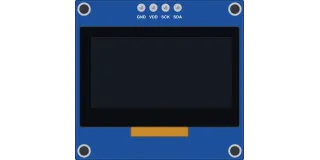
OLED display 1.3" 128×64 SH1106, I2C (4 pins)
Sino Wealth SH11064 pinspartly verified
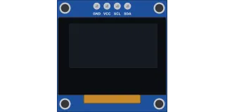
OLED 0,96" 128×64 I2C SSD1306 (GND, VCC, SCL, SDA)
SSD13064 pinspartly verified
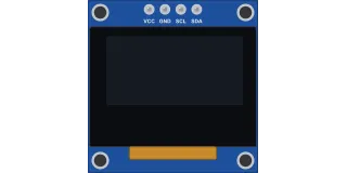
OLED 0.96" 128×64 I2C (order VCC, GND)
SSD1306 or SH11064 pinspartly verified
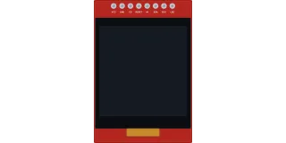
1.44" 128×128 ST7735S display, SPI (red board, 8 pins)
Sitronix ST7735S8 pinspartly verified
2.0" IPS display 240×320 ST7789, SPI (8 pins)
Sitronix ST7789V8 pinspartly verified
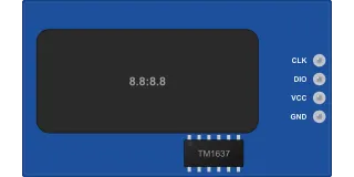
TM1637 4-digit display (CLK, DIO, VCC, GND)
Titan Micro TM16374 pinspartly verified
Audio
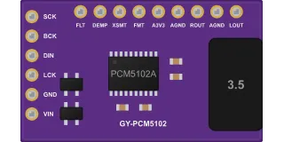
GY-PCM5102, PCM5102A I2S DAC (purple)
TI PCM5102A15 pinspartly verified
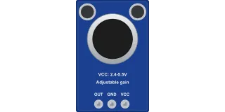
MAX4466 microphone with amplifier (Adafruit 1063)
Maxim MAX44663 pins
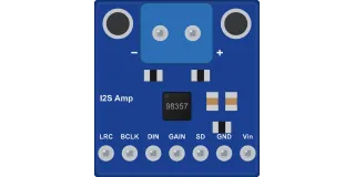
MAX98357A, 3 W I2S amplifier (Adafruit 3006)
Maxim MAX98357A9 pins
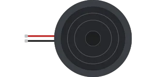
Speaker 4–8 Ω, Ø40 mm, 2 pins
dynamic driver2 pinspartly verified
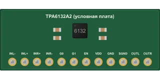
TPA6132A2 headphone amplifier (generic board from the TI datasheet)
TI TPA6132A212 pinsdraft
Motors and actuators
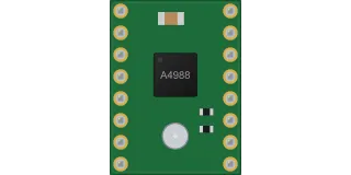
A4988 stepper motor driver (StepStick, Pololu and clones)
Allegro A498816 pins
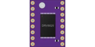
DRV8825 stepper motor driver (StepStick, Pololu and clones)
TI DRV882516 pins
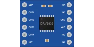
DRV8833, dual motor driver (HW-627 module, 12 pins)
TI DRV883312 pinspartly verified
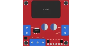
L298N motor driver (red module with heatsink)
ST L298N13 pinspartly verified
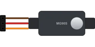
MG90S servo (TowerPro, metal gears)
PWM-controlled servo3 pinspartly verified
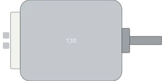
Motor 130 (toy, 4.5-9 V), 2 pins
brushed motor without gearbox2 pinspartly verified
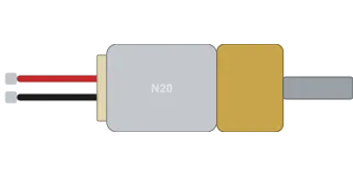
N20 gear motor (12×10 mm), 2 pins
3–12 V brushed motor with a gearbox2 pinspartly verified
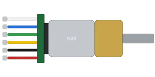
N20 gear motor with Hall encoder, 6 pins
brushed motor with gearbox and magnetic encoder6 pinspartly verified
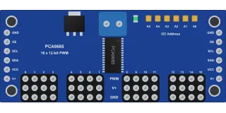
PCA9685, 16-servo I2C driver (Adafruit 815)
NXP PCA968562 pins
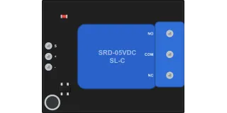
1-channel 5 V relay module without optocoupler (KY-019, triggers on HIGH)
Songle SRD-05VDC-SL-C relay6 pinspartly verified
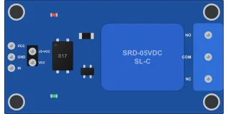
1-channel 5 V relay module with optocoupler (active LOW, JD-VCC jumper)
Songle SRD-05VDC-SL-C relay + PC817 optocoupler8 pinspartly verified
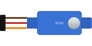
SG90 servo (TowerPro, 9 g)
PWM-controlled servo3 pins
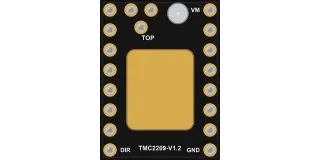
TMC2209 stepper motor driver (StepStick, BIGTREETECH V1.2)
Trinamic (ADI) TMC220919 pins
Power: batteries and cells
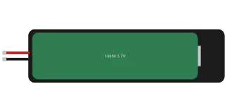
18650 battery in a 1-cell holder (3.7 V, with wires)
Li-ion 18650, 1 pcs.2 pinspartly verified
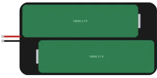
Two 18650 cells in a holder in series (7.4 V, with wires)
Li-ion 18650, 2 pcs in series (2S)2 pinspartly verified
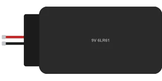
9 V PP3 battery (6LR61) with clip
Alkaline 9 V (6LR61)2 pinspartly verified
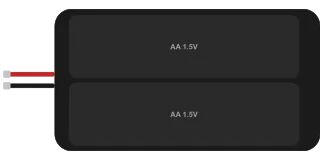
2×AA battery holder (3 V, with wires)
2 × AA alkaline in series2 pinspartly verified
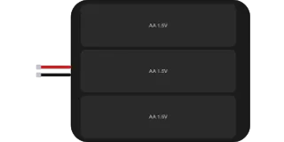
3×AA battery holder (4.5 V, with wires)
3 × AA alkaline in series2 pinspartly verified
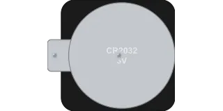
CR2032 battery in a PCB holder (3 V)
Lithium CR20322 pinspartly verified
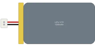
LiPo 1S 3.7 V battery with a JST-PH 2.0 connector (1200 mAh)
Li-polymer 1S2 pinspartly verified
Power: regulators
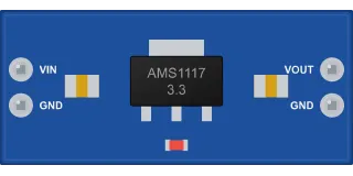
AMS1117-3.3 regulator (blue 25×11 module, 4 pins)
AMS1117-3.34 pinspartly verified
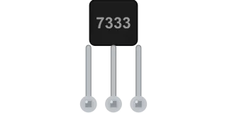
HT7333 regulator (3.3 V, 250 mA, TO-92)
HT73333 pinspartly verified
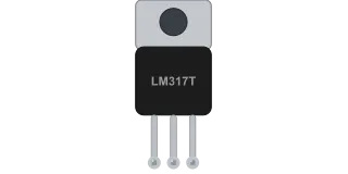
LM317 adjustable regulator (1.25–37 V, TO-220)
LM3173 pins
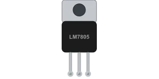
LM7805 regulator (5 V, TO-220)
LM78053 pins
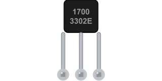
MCP1700-3302E/TO regulator (3.3 V, 250 mA, TO-92)
MCP1700-3302E3 pins
Power: DC-DC converters
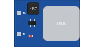
Boost module 0.9–5 V → 5 V with a USB socket (600 mA)
unmarked (boost controller, SOT-23)4 pinspartly verified
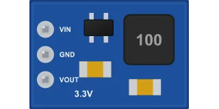
DD4012SA mini buck module, 3.3 V (up to 1 A, 3 pins)
unmarked (controller in SOT-23-6)3 pinspartly verified
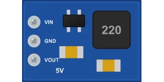
DD4012SA mini buck module for 5 V (up to 1 A, 3 pins)
unmarked (controller in SOT-23-6)3 pinspartly verified
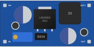
LM2596 buck module (blue 43×21, trimmer, up to 2-3 A)
LM2596S-ADJ4 pinspartly verified
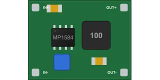
MP1584EN mini step-down module (22×17, 1.5–3 A)
MP1584EN4 pinspartly verified
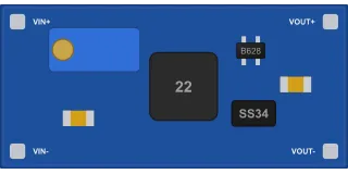
MT3608 boost module (36×17, "2 A", trimmer)
MT36084 pinspartly verified
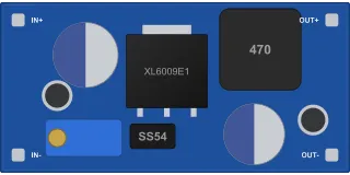
XL6009 boost module (43×21, up to 4 A switch)
XL6009E14 pinspartly verified
Power: charging, protection, USB-C
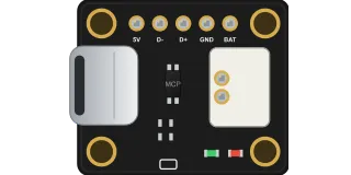
Adafruit Micro-Lipo USB-C LiPo charger (MCP73831, product 4410)
MCP73831T-2ACI/OT7 pins
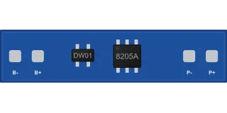
BMS 1S protection board (3.7 V, DW01 + 8205A)
DW01A + FS8205A4 pinspartly verified
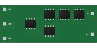
BMS 2S protection board (7.4 V, with balancing)
2S protection controller (HY2120/HY2213 and equivalents) + MOSFET5 pinspartly verified
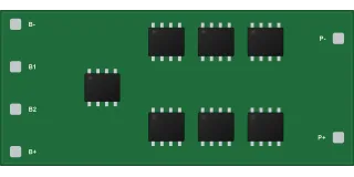
BMS 3S protection board (11.1 V, with balancing)
3S protection controller (HY2120/HY2213 and equivalents) + MOSFET6 pinspartly verified
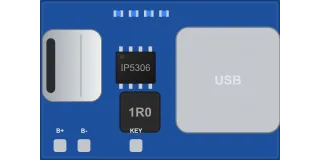
IP5306 power bank module (2 A charging + 5 V 2 A output, USB-C and USB-A)
IP53065 pinspartly verified
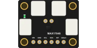
MAX17048, LiPo fuel gauge (Adafruit 5580)
Maxim MAX170488 pins
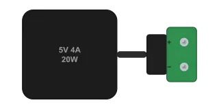
5 V 4 A power supply (5.5×2.1 plug, adapter to screw terminals)
Mean Well GST25E05-P1J2 pinspartly verified
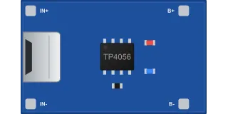
TP4056 charger without protection (4 pads, micro-USB)
TP40564 pinspartly verified
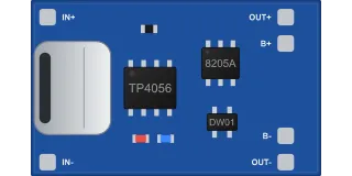
TP4056 charger with protection (DW01A + 8205A, USB-C)
TP4056 + DW01A + FS8205A6 pinspartly verified
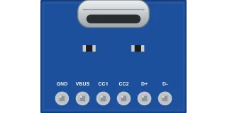
USB-C 16P breakout to pins (VBUS, GND, CC1, CC2, D+, D−)
USB Type-C 16P receptacle (USB 2.0)6 pinspartly verified
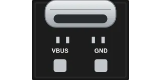
USB-C power-only breakout (6P connector, VBUS and GND, 5.1 kΩ resistors)
USB Type-C 6P socket (VBUS ×2, GND ×2, CC1, CC2)2 pinspartly verified
Memory cards
How to read a pinout
On a board page, clicking a pin opens its card: functions (ADC, PWM, I2C, SPI, UART), limitations and the source it was checked against. The buttons above the drawing highlight pins: "boot" shows strapping pins, "do not use" the flash and PSRAM pins, "unverified" the pins not confirmed by the manufacturer's documents. Below the drawing are the "Important" block, a table of all pins and a "Download PNG" button.
The chip reads strapping pins at power-up and uses them to choose the boot mode and some settings: on an ESP32 these are GPIO0, 2, 5, 12 and 15, on an ESP8266 GPIO0, 2 and 15, on an ESP32-C3 GPIO2, 8 and 9. The "input only" mark on an ESP32 sits on GPIO34-39, which have no output driver and no pulls. The mark "ADC2 does not work with Wi-Fi on" sits on the ESP32 ADC2 pins; with Wi-Fi, take ADC1 on GPIO32-39 for analog readings.
Examples
- On the 30-pin ESP32 DOIT DevKit V1, GPIO0 and the flash pins GPIO6-11 are not brought out to the header. D2, D5, D12 and D15 are marked as strapping, D34, D35, VP and VN as input only.
- ESP32-C3 SuperMini: the LED is on GPIO8 and the BOOT button on GPIO9, both strapping pins. In Arduino they are also the default SDA and SCL, so the LED blinks while I2C is running.
Common mistakes
- People hang a module on GPIO12 of an ESP32 that pulls the pin high at power-up. The chip then sets the flash supply to 1.8 V, and a module with 3.3 V flash won't boot.
- People read the ADC on GPIO25-27 with Wi-Fi on. Those pins belong to ADC2, and the reading doesn't work.
FAQ
- Which ESP32 pins can I use without restrictions?
- On the DevKitC and DOIT DevKit V1, according to the site's data, GPIO4, 13, 14, 16-19, 21-23, 25-27, 32 and 33 work without caveats; on 4, 13, 14 and 25-27 only the ADC doesn't work with Wi-Fi. GPIO0, 2, 5, 12 and 15 work after boot if they are at the right level at power-up. GPIO6-11 are used by flash, GPIO1 and 3 by the USB-UART port.
- Can I put 5 V on the pins of an ESP32, ESP8266 or Pico?
- Not on an ESP32 or ESP8266. According to the Espressif datasheet the ESP32's input limit is VDD + 0.3 V, which is 3.6 V with a 3.3 V supply, and the ESP8266's limit is also 3.6 V. The Raspberry Pi Pico with the RP2040 does not tolerate 5 V on GPIO; on the Pico 2 with the RP2350 the inputs tolerate 5 V when the chip is powered, except the ADC pins GP26-GP28. Take a 5 V signal through a divider or a level shifter.
- What is the difference between the 30-pin and 38-pin ESP32 DevKit?
- The chip and most GPIOs are the same. The 38-pin version brings out GPIO0, the flash pins GPIO6-11 (which you don't use) and one more GND to the header. The 30-pin DOIT DevKit V1 doesn't have them, and GPIO0 there is only on the BOOT button. Both have rows 25.4 mm apart.
- What do the "verified" and "partly verified" labels mean?
- "Verified" is set on a board all of whose pins are confirmed by the manufacturer's documents. On "partly verified", some pins are confirmed by other sources; the card of such a pin says what confirms it and where the sources disagree. The date of the check is shown next to the label.