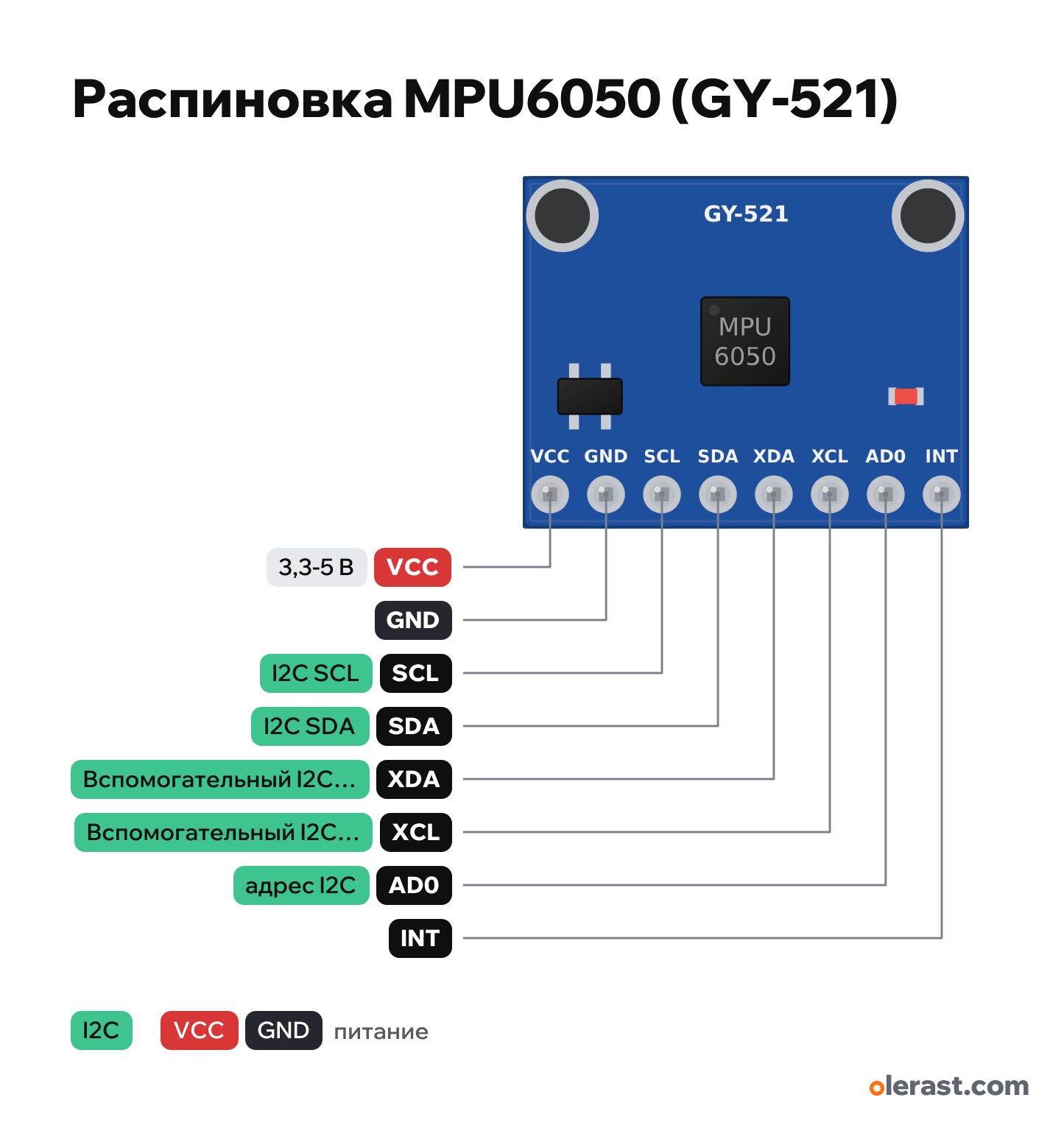
MPU6050 (GY-521) pinout
MPU-6050 GY-521 (accelerometer + gyroscope), InvenSense MPU-6050, 3.3 V logic, 20.26×16 mm, 8 pins
partly verified15.10.2026
Front view (sensor side), connector at the bottom.
Download PNG- Chip
- InvenSense MPU-6050
- Logic
- 3.3 V
- Power
- VCC 3.3-5 V
- I2C address
- 0x68second 0x69: AD0 to VCC
Important
- Power 3.3-5 V through the on-board regulator (from 3.3 V the headroom may not be enough, 5 V is better).
- Address 0x68 (AD0 to ground) or 0x69.
- Chip clones return a WHO_AM_I other than 0x68: some libraries decide the sensor is missing.
- Geometry from independent KiCad footprints and photos (±0.3 mm). Holes and small components are approximate, check with calipers.
All pins
| Label | Number | Functions | Limits | Check |
|---|---|---|---|---|
| VCC | 5 V | power input | not from manufacturerNo-name module: the order matches in two descriptions and three footprints. | |
| GND | Ground | not from manufacturerNo-name module: the order matches in two descriptions and three footprints. | ||
| SCL | I2C SCL | onboard pull-up | not from manufacturerNo-name module: the order matches in two descriptions and three footprints.Pull-up on the board (2.2 or 10 kΩ in different batches); to 3.3 V or to VCC, sources disagree. | |
| SDA | I2C SDA | onboard pull-up | not from manufacturerNo-name module: the order matches in two descriptions and three footprints. | |
| XDA | Auxiliary I2C SDA (master, for a magnetometer) | not from manufacturerNo-name module: the order matches in two descriptions and three footprints. | ||
| XCL | Auxiliary I2C SCL (master) | not from manufacturerNo-name module: the order matches in two descriptions and three footprints. | ||
| AD0 | I2C address: low 0x68, high 0x69 | onboard pull-down | not from manufacturerNo-name module: the order matches in two descriptions and three footprints.4.7 kΩ pull-down to ground: 0x68 by default. To 3.3 V it is 0x69 (not to 5 V).Labelled on other revisions as: ADO | |
| INT | INT: interrupt output (data ready, motion) | not from manufacturerNo-name module: the order matches in two descriptions and three footprints. |
Sources
Not verified against the manufacturer: 8 of 8 pins. The pin card says what confirms each one and where sources disagree.
- InvenSense MPU-6000/6050 Product Specification Rev 3.1 (SparkFun copy)datasheet, checked 15.10.2026VDD 2.375-3.46 V, I2C up to 400 kHz, address 0b110100X (AD0), auxiliary I2C, INT
- ProtoSupplies: MPU-6050 GY-521third-party source, checked 15.10.2026order VCC, GND, SCL, SDA, XDA, XCL, AD0, INT; 21×16 mm; AD0 4.7 kΩ to ground
- LastMinuteEngineers: MPU6050 tutorial (board photo)third-party source, checked 15.10.2026same order, regulator, LED, holes
- Arduino Playground: MPU-6050third-party source, checked 15.10.2026power is better at 5 V (regulator), pull-ups 2.2 or 10 kΩ
- KiCad: ciaa/Ponchos GY-521, opatiny/micromouse GY-521third-party source, checked 15.10.2026size 20.26×16.0, row 1.55 mm from the edge, 2.54 pitch
Size: from the KiCad footprint (ciaa); ProtoSupplies lists 21×16 (approximate).
FAQ
- What is the I2C address of the MPU6050 (GY-521)?
- 0x68. Tie AD0 to VCC and the address becomes 0x69. SDA and SCL pull-ups are on the module.
- What supply voltage does the MPU6050 (GY-521) need?
- VCC: 3.3-5 V. 3.3 V logic.