DHT11 module KY-015 pinout
DHT11 module KY-015 (S, +V, −), DHT11, 3.3 V logic, 16×22.5 mm, 3 pins
partly verified20.10.2026
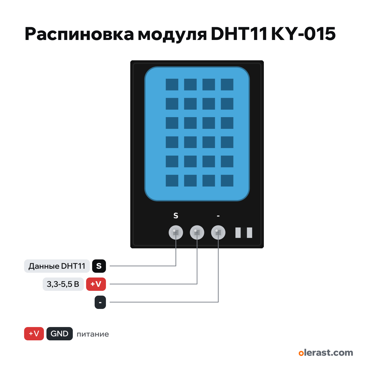
Top view, sensor on top, header at the bottom: S, +V, − left to right (as in the Joy-IT wiring diagram).
Download PNG- Chip
- DHT11
- Logic
- 3.3 V
- Power
- +V (middle pin) 3.3-5.5 V
Important
- The KY-015 order is the reverse of the KY-001: here S is on the left, − on the right.
- To an ESP32: +V to 3V3, S to a GPIO with output (not 34-39), − to GND. The pull-up is on the board.
- To an Arduino: +V to 5V, S to D2 (Joy-IT example).
- Poll no more than once every 2 seconds.
- Board and parts are drawn from Joy-IT photos, dimensions not measured.
Revisions and clones
- Blue DHT11 modules without a KY number: labels "+", "out", "−" or VCC, DATA, GND; Components101 gives the order Vcc, Data, Ground.
All pins
| Label | Number | Functions | Limits | Check |
|---|---|---|---|---|
| S | DHT11 data (Aosong bus) | onboard pull-up | not from manufacturerThere is no module schematic: the order is from the Joy-IT wiring diagram (S, +V, −). Blue modules from other sellers have a different order and labels (+, out, −). The R1 value is not stated. Check the labels on your board.R1 pull-up to +V on the board: no external resistor needed.Labelled on other revisions as: Signal, DATA, OUT, DAT | |
| +V | 3.3 V | power input | not from manufacturerThere is no module schematic: the order is from the Joy-IT wiring diagram (S, +V, −). Blue modules from other sellers have a different order and labels (+, out, −). The R1 value is not stated. Check the labels on your board.The middle pin is unlabeled on the board.Labelled on other revisions as: VCC, + | |
| - | Ground | not from manufacturerThere is no module schematic: the order is from the Joy-IT wiring diagram (S, +V, −). Blue modules from other sellers have a different order and labels (+, out, −). The R1 value is not stated. Check the labels on your board.Labelled on other revisions as: −, GND |
Sources
Not verified against the manufacturer: 3 of 3 pins. The pin card says what confirms each one and where sources disagree.
- Joy-IT KY015 DHT11 Temperature sensor, datasheet (24.08.2023)user guide, checked 20.10.2026DHT11, 3.0-5.5 V, 16×27×9 mm, poll once every 2 s; the photo shows R1 and the S label by the header
- Joy-IT KY-015 DHT11 Temperature sensor, manual (22.03.2024)user guide, checked 20.10.2026wiring diagram: S on the left, +V in the middle, − on the right; Signal to D2, +V to 5V on Arduino, to 3.3 V on Raspberry Pi
- Aosong (Guangzhou) DHT11 digital temperature and humidity sensor V1.3 (31.03.2017, LCSC copy)datasheet, checked 20.10.2026pins 1 VDD (3.3–5.5 V), 2 DATA, 3 NC, 4 GND left to right when facing the grille; package 12.5×16×6 mm, 2.54 mm pitch; current 0.06 mA standby, up to 1.0 mA while measuring; poll period over 2 s; 4.7 kΩ pull-up for wire under 5 m; 5–95 %RH ±5 %, -20...60 °C ±2 °C
Size: 16×27×9 mm with the header per Joy-IT; the board and parts are taken from photos, not dimensioned (approximate).
FAQ
- What supply voltage does the DHT11 module KY-015 need?
- +V (middle pin): 3.3-5.5 V. 3.3 V logic.