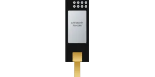
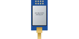
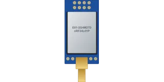
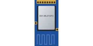
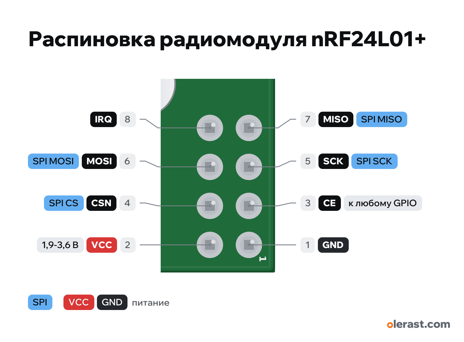
nRF24L01+ pinout
nRF24L01+ (module with an on-board antenna), nRF24L01+ (Nordic), 3.3 V logic, 15×29 mm, 8 pins
partly verified15.10.2026
Top view (chip side), connector at the top, antenna at the bottom, rotated 90° on the diagram.
CompareDownload PNG- Chip
- nRF24L01+ (Nordic)
- Logic
- 3.3 V
- Power
- VCC 1.9-3.6 V
Important
- Supply only 1.9–3.6 V. The module burns out on 5 V.
- 10 µF capacitor (electrolytic or tantalum) right at the module VCC and GND pins: without it the link is unstable, especially from the Arduino 3.3 V pin.
- SPI up to 10 MHz, mode 0. CE and CSN can be any GPIO.
- Pin 1 (GND) is the square pad, at the top right in the drawing. Odd pins are at the board edge, even pins in the second row.
- Current: TX 11.3 mA at 0 dBm, RX 13.5 mA.
Revisions and clones
- Clones may use the Si24R1 (command-compatible, but not in everything). The pinout is the same.
- There are adapters with a 3.3 V regulator for this header: then 5 V is fed to the adapter, not to the module.
All pins
| Label | Number | Functions | Limits | Check |
|---|---|---|---|---|
| GND | pin 1 | Ground | not from manufacturerThe module has no manufacturer with documentation: the order 1-8 is the same in all sources, the geometry is taken from the Elechouse drawing without dimension lines (±0.3 mm). | |
| VCC | pin 2 | 3.3 V | power input | not from manufacturerThe module has no manufacturer with documentation: the order 1-8 is the same in all sources, the geometry is taken from the Elechouse drawing without dimension lines (±0.3 mm).1.9-3.6 V (Nordic). Do not apply 5 V. |
| CE | pin 3 | CE: enable receive/transmit (active high) | 5 V tolerant | not from manufacturerThe module has no manufacturer with documentation: the order 1-8 is the same in all sources, the geometry is taken from the Elechouse drawing without dimension lines (±0.3 mm).The input tolerates 5 V when the module is powered at 2.7–3.3 V (Nordic). |
| CSN | pin 4 | SPI CS (CSN, active low) | 5 V tolerant | not from manufacturerThe module has no manufacturer with documentation: the order 1-8 is the same in all sources, the geometry is taken from the Elechouse drawing without dimension lines (±0.3 mm).The input tolerates 5 V when the module is powered at 2.7–3.3 V (Nordic). |
| SCK | pin 5 | SPI SCK | 5 V tolerant | not from manufacturerThe module has no manufacturer with documentation: the order 1-8 is the same in all sources, the geometry is taken from the Elechouse drawing without dimension lines (±0.3 mm).The input tolerates 5 V when the module is powered at 2.7–3.3 V (Nordic). |
| MOSI | pin 6 | SPI MOSI (module input) | 5 V tolerant | not from manufacturerThe module has no manufacturer with documentation: the order 1-8 is the same in all sources, the geometry is taken from the Elechouse drawing without dimension lines (±0.3 mm).The input tolerates 5 V when the module is powered at 2.7–3.3 V (Nordic). |
| MISO | pin 7 | SPI MISO (module output) | not from manufacturerThe module has no manufacturer with documentation: the order 1-8 is the same in all sources, the geometry is taken from the Elechouse drawing without dimension lines (±0.3 mm).Module output: level equals the module supply (3.3 V). Usually enough for the input of a 5 V MCU. | |
| IRQ | pin 8 | IRQ: interrupt (active low)to the MCU interrupt pin | not from manufacturerThe module has no manufacturer with documentation: the order 1-8 is the same in all sources, the geometry is taken from the Elechouse drawing without dimension lines (±0.3 mm).Can be left unconnected if you poll the status over SPI. |
Sources
Not verified against the manufacturer: 8 of 8 pins. The pin card says what confirms each one and where sources disagree.
- Nordic nRF24L01+ Product Specification v1.0 (SparkFun copy)datasheet, checked 15.10.2026pin functions CE, CSN, SCK, MOSI, MISO, IRQ; VDD 1.9–3.6 V; inputs tolerate 5 V (VIH up to 5.25 V) at VDD 2.7–3.3 V; TX current 11.3 mA at 0 dBm, RX 13.5 mA; supply decoupling
- Elechouse: NRF24L01 module (layout drawing, numbering 1-8)third-party source, checked 15.10.2026size 15.01×29.01 mm, 2×4 header at the short edge opposite the antenna, pin 1 (GND) is square, order 1 GND ... 8 IRQ
- RF24 library: COMMON_ISSUES.mdthird-party source, checked 15.10.202610 µF capacitor at the module supply pins; PA+LNA modules need a strong power source
Size: from the Elechouse layout drawing (15.01×29.01), clones are 15-15.2×28.5-29 (approximate).
FAQ
- What supply voltage does the nRF24L01+ need?
- VCC: 1.9-3.6 V. 3.3 V logic.