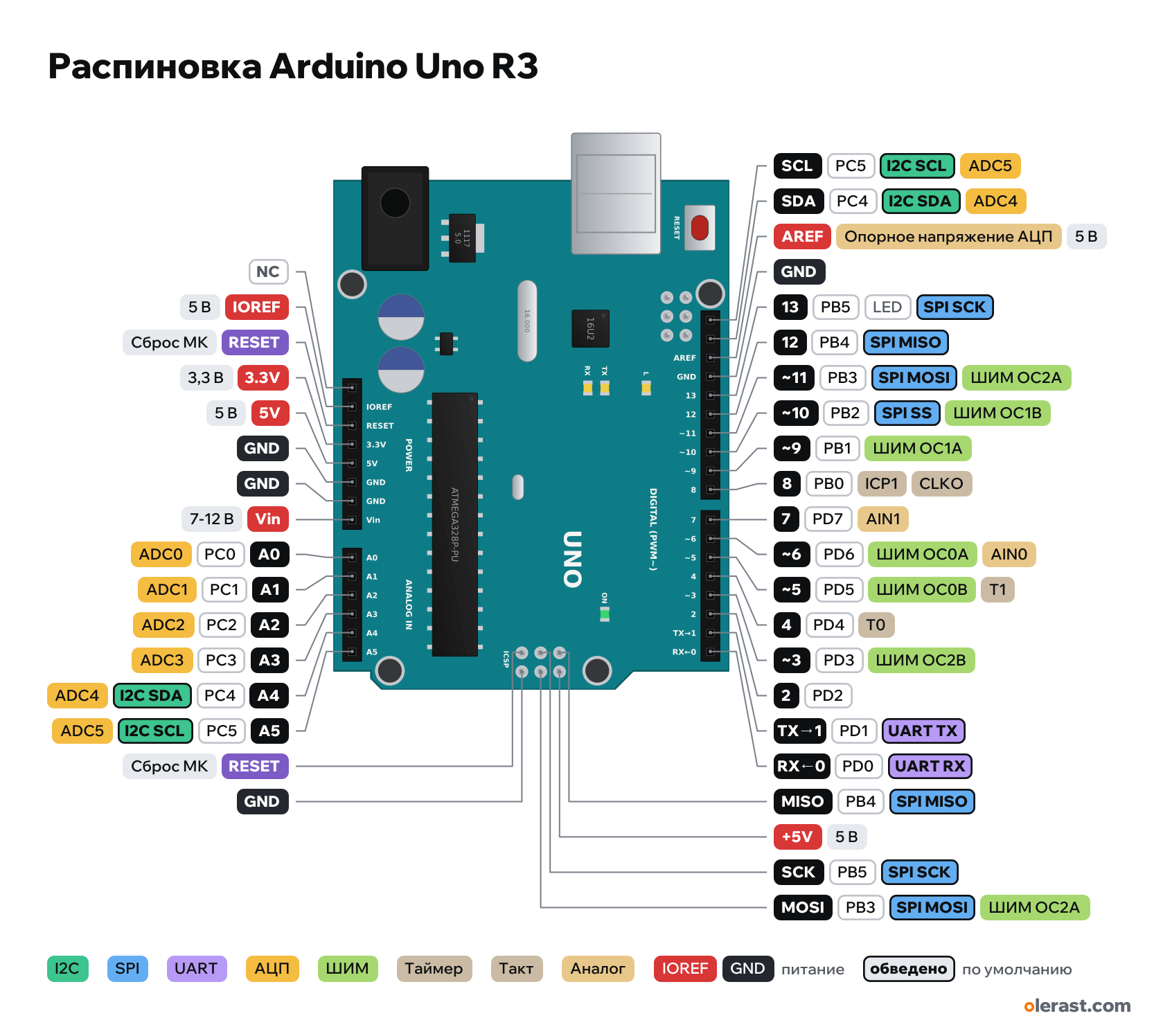
Arduino Uno R3 pinout
Arduino Uno R3, ATmega328P, 5 V logic, 68.58×53.34 mm, 44 pins
verified15.10.2026
- NC
- IOREF5 V
- RESETMCU reset
- 3.3V3.3 V
- 5V5 V
- GND
- GND
- Vin7-12 V
- A0PC014ADC0
- A1PC115ADC1
- A2PC216ADC2
- A3PC317ADC3
- A4PC418I2C SDAADC4
- A5PC519I2C SCLADC5
- RESETMCU reset
- GND
- SCLPC5I2C SCLADC5
- SDAPC4I2C SDAADC4
- AREFADC reference voltage5 V
- GND
- 13PB5LEDSPI SCK
- 12PB4SPI MISO
- ~11PB311SPI MOSIPWM OC2A
- ~10PB210SPI SSPWM OC1B
- ~9PB19PWM OC1A
- 8PB0ICP1CLKO
- 7PD7AIN1
- ~6PD66PWM OC0AAIN0
- ~5PD55PWM OC0BT1
- 4PD4T0
- ~3PD33PWM OC2B
- 2PD2
- TX→1PD11UART TX
- RX←0PD00UART RX
- MISOPB4SPI MISO
- +5V5 V
- SCKPB5SPI SCK
- MOSIPB3SPI MOSIPWM OC2A
Top view, USB and DC jack on the left, digital pins at the top, rotated 90° on the diagram.
BuyCompareDownload PNG- Chip
- ATmega328P
- Logic
- 5 V
- Power
- USB-B 4.75-5.25 VDC jack 5.5×2.1 mm 7-12 VVin 7-12 V
- Defaults in Arduino AVR core
- I2C: SDA 18, SCL 19SPI: MOSI 11, MISO 12, SCK 13, SS 10UART: TX 1, RX 0LED: 13
Which Arduino Uno R3 pins are safe to use
Free to use
D0-D12, A0-A5
Use with care
- D13: onboard LED.
Important
- 5 V logic. Connect 3.3 V modules (ESP, nRF24, many sensors) through a divider or a level shifter.
- D0 and D1 are connected to the ATmega16U2 through 1 kΩ resistors: while they are in use, flashing and Serial do not work.
- PWM: 3, 5, 6, 9, 10, 11 (~ symbol). On 5 and 6 the frequency is ~980 Hz, on the others ~490 Hz.
- I2C: A4 (SDA) and A5 (SCL), also broken out separately next to AREF.
- Current per pin up to 20 mA, limit 40 mA, no more than 200 mA across all pins together.
- Between pins 7 and 8 there is a nonstandard 4.06 mm (160 mil) gap: a breadboard will not fit both headers.
Revisions and clones
- Uno clones with the CH340G: a CH340 bridge instead of the ATmega16U2, no ICSP1, often an SMD ATmega328P (then A6 and A7 are on separate pads). The pins of the main headers are the same.
- Uno R3 SMD: ATmega328P in a TQFP package, same connectors.
All pins
| Label | Number | Functions | Limits | Check |
|---|---|---|---|---|
| SCL | PC5 | ADC5I2C SCLPCINT (pin change interrupt) | verifiedCurrent per pin: up to 20 mA operating, 40 mA limit, less for the whole port (datasheet, Absolute Maximum Ratings).Separate I2C SCL pin, connected to A5. Not labeled on the front. | |
| SDA | PC4 | ADC4I2C SDAPCINT (pin change interrupt) | verifiedCurrent per pin: up to 20 mA operating, 40 mA limit, less for the whole port (datasheet, Absolute Maximum Ratings).Separate I2C SDA pin, connected to A4. Not labeled on the front. | |
| AREF | 5 VADC reference voltage | power input | verifiedExternal reference for analogRead (analogReference(EXTERNAL)). No higher than 5 V. | |
| GND | Ground | verified | ||
| 13 | PB5, Arduino 13 | SPI SCKPCINT (pin change interrupt) | onboard LED | verifiedCurrent per pin: up to 20 mA operating, 40 mA limit, less for the whole port (datasheet, Absolute Maximum Ratings).The L LED is connected through an LMV358 buffer and barely affects the pin. |
| 12 | PB4, Arduino 12 | SPI MISOPCINT (pin change interrupt) | verifiedCurrent per pin: up to 20 mA operating, 40 mA limit, less for the whole port (datasheet, Absolute Maximum Ratings). | |
| ~11 | PB3, Arduino 11 | PWM OC2A (Timer2)SPI MOSIPCINT (pin change interrupt) | verifiedCurrent per pin: up to 20 mA operating, 40 mA limit, less for the whole port (datasheet, Absolute Maximum Ratings). | |
| ~10 | PB2, Arduino 10 | PWM OC1B (Timer1)SPI SSPCINT (pin change interrupt) | verifiedCurrent per pin: up to 20 mA operating, 40 mA limit, less for the whole port (datasheet, Absolute Maximum Ratings). | |
| ~9 | PB1, Arduino 9 | PWM OC1A (Timer1)PCINT (pin change interrupt) | verifiedCurrent per pin: up to 20 mA operating, 40 mA limit, less for the whole port (datasheet, Absolute Maximum Ratings). | |
| 8 | PB0, Arduino 8 | ICP1 (Timer1 capture)CLKOPCINT (pin change interrupt) | verifiedCurrent per pin: up to 20 mA operating, 40 mA limit, less for the whole port (datasheet, Absolute Maximum Ratings). | |
| 7 | PD7, Arduino 7 | AIN1 (comparator −)PCINT (pin change interrupt) | verifiedCurrent per pin: up to 20 mA operating, 40 mA limit, less for the whole port (datasheet, Absolute Maximum Ratings). | |
| ~6 | PD6, Arduino 6 | PWM OC0A (Timer0, ~980 Hz)AIN0 (comparator +)PCINT (pin change interrupt) | verifiedCurrent per pin: up to 20 mA operating, 40 mA limit, less for the whole port (datasheet, Absolute Maximum Ratings). | |
| ~5 | PD5, Arduino 5 | PWM OC0B (Timer0, ~980 Hz)T1 (Timer1 counter input)PCINT (pin change interrupt) | verifiedCurrent per pin: up to 20 mA operating, 40 mA limit, less for the whole port (datasheet, Absolute Maximum Ratings). | |
| 4 | PD4, Arduino 4 | T0 (Timer0 counter input)PCINT (pin change interrupt) | verifiedCurrent per pin: up to 20 mA operating, 40 mA limit, less for the whole port (datasheet, Absolute Maximum Ratings). | |
| ~3 | PD3, Arduino 3 | PWM OC2B (Timer2)INT1 (attachInterrupt 1)PCINT (pin change interrupt) | verifiedCurrent per pin: up to 20 mA operating, 40 mA limit, less for the whole port (datasheet, Absolute Maximum Ratings). | |
| 2 | PD2, Arduino 2 | INT0 (attachInterrupt 0)PCINT (pin change interrupt) | verifiedCurrent per pin: up to 20 mA operating, 40 mA limit, less for the whole port (datasheet, Absolute Maximum Ratings). | |
| TX→1 | PD1, Arduino 1 | UART TX (TXD)PCINT (pin change interrupt) | verifiedConnected to the board's USB-UART through a resistor: keep it free when flashing and using Serial.Current per pin: up to 20 mA operating, 40 mA limit, less for the whole port (datasheet, Absolute Maximum Ratings). | |
| RX←0 | PD0, Arduino 0 | UART RX (RXD)PCINT (pin change interrupt) | verifiedConnected to the board's USB-UART through a resistor: keep it free when flashing and using Serial.Current per pin: up to 20 mA operating, 40 mA limit, less for the whole port (datasheet, Absolute Maximum Ratings). | |
| - | not connected | verifiedNot connected (reserved). | ||
| IOREF | 5 V | power output | verifiedBoard logic voltage (5 V) for shields. | |
| RESET | MCU reset (low = reset) | verified | ||
| 3.3V | 3.3 V | power output | verified3.3 V regulator output, up to 50 mA (datasheet A000066). | |
| 5V | 5 V | power inputpower output | verified5 V output from the regulator or USB. You can feed 5 V in here, but it bypasses the board's protection. | |
| GND | Ground | verified | ||
| GND | Ground | verified | ||
| Vin | 9 V | power input | verified5 V regulator input: 7–12 V recommended, 6–20 V limit. When powered from the DC jack, this pin carries its voltage. | |
| A0 | PC0, Arduino A0 (14) | ADC0PCINT (pin change interrupt) | verifiedCurrent per pin: up to 20 mA operating, 40 mA limit, less for the whole port (datasheet, Absolute Maximum Ratings). | |
| A1 | PC1, Arduino A1 (15) | ADC1PCINT (pin change interrupt) | verifiedCurrent per pin: up to 20 mA operating, 40 mA limit, less for the whole port (datasheet, Absolute Maximum Ratings). | |
| A2 | PC2, Arduino A2 (16) | ADC2PCINT (pin change interrupt) | verifiedCurrent per pin: up to 20 mA operating, 40 mA limit, less for the whole port (datasheet, Absolute Maximum Ratings). | |
| A3 | PC3, Arduino A3 (17) | ADC3PCINT (pin change interrupt) | verifiedCurrent per pin: up to 20 mA operating, 40 mA limit, less for the whole port (datasheet, Absolute Maximum Ratings). | |
| A4 | PC4, Arduino A4 (18) | ADC4I2C SDAPCINT (pin change interrupt) | verifiedCurrent per pin: up to 20 mA operating, 40 mA limit, less for the whole port (datasheet, Absolute Maximum Ratings). | |
| A5 | PC5, Arduino A5 (19) | ADC5I2C SCLPCINT (pin change interrupt) | verifiedCurrent per pin: up to 20 mA operating, 40 mA limit, less for the whole port (datasheet, Absolute Maximum Ratings). | |
| MISO | PB4 | SPI MISOPCINT (pin change interrupt) | verifiedCurrent per pin: up to 20 mA operating, 40 mA limit, less for the whole port (datasheet, Absolute Maximum Ratings).Same signal as D12. | |
| +5V | 5 V | power inputpower output | verified | |
| SCK | PB5 | SPI SCKPCINT (pin change interrupt) | verifiedCurrent per pin: up to 20 mA operating, 40 mA limit, less for the whole port (datasheet, Absolute Maximum Ratings).Same signal as D13. | |
| MOSI | PB3 | PWM OC2A (Timer2)SPI MOSIPCINT (pin change interrupt) | verifiedCurrent per pin: up to 20 mA operating, 40 mA limit, less for the whole port (datasheet, Absolute Maximum Ratings).Same signal as D11. | |
| RESET | MCU reset (low = reset) | verified | ||
| GND | Ground | verified | ||
| MISO2 | ATmega16U2 MISO | verifiedProgramming of the ATmega16U2 USB controller. Not needed for sketches. | ||
| +5V | 5 V | power inputpower output | verified | |
| SCK2 | ATmega16U2 SCK | verified | ||
| MOSI2 | ATmega16U2 MOSI | verified | ||
| RESET2 | ATmega16U2 reset | verified | ||
| GND | Ground | verified |
Sources
Every pin is verified against the manufacturer's documents.
- Arduino UNO R3: Eagle files UNO-TH_Rev3e (reference design)board drawing, checked 15.10.2026size 68.58×53.34 mm, centers of all connector and ICSP pads, component positions, holes, pin nets
- Arduino UNO R3 Datasheet (A000066)datasheet, checked 15.10.2026connector and port tables, power (VIN 6–20 V, recommended 7–12 V), 3.3 V current 50 mA, holes
- ATmega328P Datasheet (Microchip DS40002061)datasheet, checked 15.10.2026alternate functions of ports B, C, D: OC0A/B, OC1A/B, OC2A/B, INT0/1, PCINT, SPI, TWI, USART, ADC0–7, AIN0/1; ADC6/7 analog only; pin currents
- ArduinoCore-avr: variants/standard/pins_arduino.hArduino core, checked 15.10.2026Arduino numbers ↔ ports, PWM on 3, 5, 6, 9, 10, 11, SS 10, MOSI 11, MISO 12, SCK 13, SDA A4, SCL A5, LED_BUILTIN 13
Size: from the Eagle file; the right edge has a protrusion.
FAQ
- Which Arduino Uno R3 pins are I2C, SPI and UART?
- By default in Arduino AVR core: I2C: SDA A4, SCL A5; SPI: MOSI D11, MISO D12, SCK D13, SS D10; UART: TX D1, RX D0.
- Which pin is the Arduino Uno R3 LED on?
- L LED on D13 (through a buffer).
You might also need
Similar boards
Next
Need firmware or a device built on Arduino? I'll build it to order