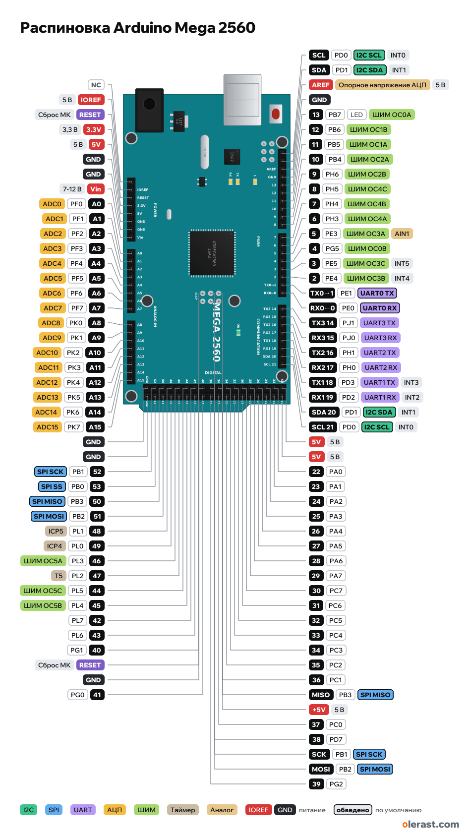
Arduino Mega 2560 pinout
Arduino Mega 2560 R3, ATmega2560, 5 V logic, 101.6×53.34 mm, 98 pins
partly verified15.10.2026
- NC
- IOREF5 V
- RESETMCU reset
- 3.3V3.3 V
- 5V5 V
- GND
- GND
- Vin7-12 V
- A0PF054ADC0
- A1PF155ADC1
- A2PF256ADC2
- A3PF357ADC3
- A4PF458ADC4
- A5PF559ADC5
- A6PF660ADC6
- A7PF761ADC7
- A8PK062ADC8
- A9PK163ADC9
- A10PK264ADC10
- A11PK365ADC11
- A12PK466ADC12
- A13PK567ADC13
- A14PK668ADC14
- A15PK769ADC15
- GND
- GND
- 52PB1SPI SCK
- 53PB0SPI SS
- 50PB3SPI MISO
- 51PB2SPI MOSI
- 48PL1ICP5
- 49PL0ICP4
- 46PL3PWM OC5A
- 47PL2T5
- 44PL5PWM OC5C
- 45PL4PWM OC5B
- 42PL7
- 43PL6
- 40PG1
- RESETMCU reset
- GND
- 41PG0
- SCLPD0I2C SCLINT0
- SDAPD1I2C SDAINT1
- AREFADC reference voltage5 V
- GND
- 13PB7LEDPWM OC0A
- 12PB6PWM OC1B
- 11PB5PWM OC1A
- 10PB4PWM OC2A
- 9PH6PWM OC2B
- 8PH5PWM OC4C
- 7PH4PWM OC4B
- 6PH3PWM OC4A
- 5PE3PWM OC3AAIN1
- 4PG5PWM OC0B
- 3PE5PWM OC3CINT5
- 2PE4PWM OC3BINT4
- TX0→1PE11UART0 TX
- RX0←0PE00UART0 RX
- TX3 14PJ114UART3 TX
- RX3 15PJ015UART3 RX
- TX2 16PH116UART2 TX
- RX2 17PH017UART2 RX
- TX1 18PD318UART1 TXINT3
- RX1 19PD219UART1 RXINT2
- SDA 20PD120I2C SDAINT1
- SCL 21PD021I2C SCLINT0
- 5V5 V
- 5V5 V
- 22PA0
- 23PA1
- 24PA2
- 25PA3
- 26PA4
- 27PA5
- 28PA6
- 29PA7
- 30PC7
- 31PC6
- 32PC5
- 33PC4
- 34PC3
- 35PC2
- 36PC1
- MISOPB3SPI MISO
- +5V5 V
- 37PC0
- 38PD7
- SCKPB1SPI SCK
- MOSIPB2SPI MOSI
- 39PG2
Top view, USB and DC jack on the left, digital pins at the top, rotated 90° on the diagram.
CompareDownload PNG- Chip
- ATmega2560
- Logic
- 5 V
- Power
- USB-B 4.75-5.25 VDC jack 5.5×2.1 mm 7-12 VVin 7-12 V
- Defaults in Arduino AVR core
- I2C: SDA 20, SCL 21SPI: MOSI 51, MISO 50, SCK 52, SS 53UART: TX 1, RX 0LED: 13
Which Arduino Mega 2560 pins are safe to use
Free to use
D0-D12, D14-D53, A0-A15
Use with care
- D13: onboard LED.
Important
- 5 V logic. Connect 3.3 V modules through a level shifter.
- SPI on the Mega: 50 MISO, 51 MOSI, 52 SCK, 53 SS (and on ICSP). Uno shields that take SPI from 11–13 don't work on the Mega without modification.
- I2C: 20 SDA, 21 SCL (A4/A5 on the Uno).
- PWM: 2–13 and 44–46. attachInterrupt interrupts: 2, 3, 18, 19, 20, 21.
- 4 UARTs: Serial (0/1, used by USB), Serial1 (19/18), Serial2 (17/16), Serial3 (15/14).
- The A000067 pinout picture marks D0 and D1 with "~", but they have no PWM (PE0/PE1 have no timer outputs).
Revisions and clones
- CH340G clones: a CH340 bridge instead of the ATmega16U2, same connectors.
All pins
| Label | Number | Functions | Limits | Check |
|---|---|---|---|---|
| SCL | PD0 | I2C SCLINT0 (attachInterrupt 2) | verifiedCurrent per pin: up to 20 mA operating, 40 mA limit (datasheet, Absolute Maximum Ratings).Separate I2C SCL pin, same net as D21. Not labeled on the front side. | |
| SDA | PD1 | I2C SDAINT1 (attachInterrupt 3) | verifiedCurrent per pin: up to 20 mA operating, 40 mA limit (datasheet, Absolute Maximum Ratings).Separate I2C SDA pin, same net as D20. Not labeled on the front side. | |
| AREF | 5 VADC reference voltage | power input | verified | |
| GND | Ground | verified | ||
| 13 | PB7, Arduino 13 | PWM OC0A (Timer0, ~980 Hz)PCINT7 | onboard LED | verifiedCurrent per pin: up to 20 mA operating, 40 mA limit (datasheet, Absolute Maximum Ratings).L LED through a buffer. |
| 12 | PB6, Arduino 12 | PWM OC1B (Timer1)PCINT6 | verifiedCurrent per pin: up to 20 mA operating, 40 mA limit (datasheet, Absolute Maximum Ratings). | |
| 11 | PB5, Arduino 11 | PWM OC1A (Timer1)PCINT5 | verifiedCurrent per pin: up to 20 mA operating, 40 mA limit (datasheet, Absolute Maximum Ratings). | |
| 10 | PB4, Arduino 10 | PWM OC2A (Timer2)PCINT4 | verifiedCurrent per pin: up to 20 mA operating, 40 mA limit (datasheet, Absolute Maximum Ratings). | |
| 9 | PH6, Arduino 9 | PWM OC2B (Timer2) | verifiedCurrent per pin: up to 20 mA operating, 40 mA limit (datasheet, Absolute Maximum Ratings). | |
| 8 | PH5, Arduino 8 | PWM OC4C (Timer4) | verifiedCurrent per pin: up to 20 mA operating, 40 mA limit (datasheet, Absolute Maximum Ratings). | |
| 7 | PH4, Arduino 7 | PWM OC4B (Timer4) | verifiedCurrent per pin: up to 20 mA operating, 40 mA limit (datasheet, Absolute Maximum Ratings). | |
| 6 | PH3, Arduino 6 | PWM OC4A (Timer4) | verifiedCurrent per pin: up to 20 mA operating, 40 mA limit (datasheet, Absolute Maximum Ratings). | |
| 5 | PE3, Arduino 5 | PWM OC3A (Timer3)AIN1 | verifiedCurrent per pin: up to 20 mA operating, 40 mA limit (datasheet, Absolute Maximum Ratings). | |
| 4 | PG5, Arduino 4 | PWM OC0B (Timer0, ~980 Hz) | verifiedCurrent per pin: up to 20 mA operating, 40 mA limit (datasheet, Absolute Maximum Ratings). | |
| 3 | PE5, Arduino 3 | PWM OC3C (Timer3)INT5 (attachInterrupt 1) | verifiedCurrent per pin: up to 20 mA operating, 40 mA limit (datasheet, Absolute Maximum Ratings). | |
| 2 | PE4, Arduino 2 | PWM OC3B (Timer3)INT4 (attachInterrupt 0) | verifiedCurrent per pin: up to 20 mA operating, 40 mA limit (datasheet, Absolute Maximum Ratings). | |
| TX0→1 | PE1, Arduino 1 | UART0 TX (Serial) | verifiedConnected to the ATmega16U2 (USB) through a 1 kΩ resistor: don't use it during flashing and Serial.Current per pin: up to 20 mA operating, 40 mA limit (datasheet, Absolute Maximum Ratings). | |
| RX0←0 | PE0, Arduino 0 | UART0 RX (Serial) | verifiedConnected to the ATmega16U2 (USB) through a 1 kΩ resistor: don't use it during flashing and Serial.Current per pin: up to 20 mA operating, 40 mA limit (datasheet, Absolute Maximum Ratings). | |
| TX3 14 | PJ1, Arduino 14 | UART3 TX (Serial3)PCINT10 | verifiedCurrent per pin: up to 20 mA operating, 40 mA limit (datasheet, Absolute Maximum Ratings). | |
| RX3 15 | PJ0, Arduino 15 | UART3 RX (Serial3)PCINT9 | verifiedCurrent per pin: up to 20 mA operating, 40 mA limit (datasheet, Absolute Maximum Ratings). | |
| TX2 16 | PH1, Arduino 16 | UART2 TX (Serial2) | verifiedCurrent per pin: up to 20 mA operating, 40 mA limit (datasheet, Absolute Maximum Ratings). | |
| RX2 17 | PH0, Arduino 17 | UART2 RX (Serial2) | verifiedCurrent per pin: up to 20 mA operating, 40 mA limit (datasheet, Absolute Maximum Ratings). | |
| TX1 18 | PD3, Arduino 18 | UART1 TX (Serial1)INT3 (attachInterrupt 5) | verifiedCurrent per pin: up to 20 mA operating, 40 mA limit (datasheet, Absolute Maximum Ratings). | |
| RX1 19 | PD2, Arduino 19 | UART1 RX (Serial1)INT2 (attachInterrupt 4) | verifiedCurrent per pin: up to 20 mA operating, 40 mA limit (datasheet, Absolute Maximum Ratings). | |
| SDA 20 | PD1, Arduino 20 | I2C SDAINT1 (attachInterrupt 3) | verifiedCurrent per pin: up to 20 mA operating, 40 mA limit (datasheet, Absolute Maximum Ratings).The board has 10 kΩ I2C pull-ups to 5 V (per the Mega 2560 R3 schematic). | |
| SCL 21 | PD0, Arduino 21 | I2C SCLINT0 (attachInterrupt 2) | verifiedCurrent per pin: up to 20 mA operating, 40 mA limit (datasheet, Absolute Maximum Ratings). | |
| - | not connected | verifiedNot connected (reserved). | ||
| IOREF | 5 V | power output | verifiedBoard logic voltage (5 V) for shields. | |
| RESET | MCU reset (low = reset) | verified | ||
| 3.3V | 3.3 V | power output | verified3.3 V regulator output, up to 50 mA (datasheet A000066). | |
| 5V | 5 V | power inputpower output | verified5 V output from the regulator or USB. You can feed 5 V in here, but it bypasses the board's protection. | |
| GND | Ground | verified | ||
| GND | Ground | verified | ||
| Vin | 9 V | power input | verified5 V regulator input: 7–12 V recommended, 6–20 V limit. When powered from the DC jack, this pin carries its voltage. | |
| A0 | PF0, Arduino A0 (54) | ADC0 | verifiedCurrent per pin: up to 20 mA operating, 40 mA limit (datasheet, Absolute Maximum Ratings). | |
| A1 | PF1, Arduino A1 (55) | ADC1 | verifiedCurrent per pin: up to 20 mA operating, 40 mA limit (datasheet, Absolute Maximum Ratings). | |
| A2 | PF2, Arduino A2 (56) | ADC2 | verifiedCurrent per pin: up to 20 mA operating, 40 mA limit (datasheet, Absolute Maximum Ratings). | |
| A3 | PF3, Arduino A3 (57) | ADC3 | verifiedCurrent per pin: up to 20 mA operating, 40 mA limit (datasheet, Absolute Maximum Ratings). | |
| A4 | PF4, Arduino A4 (58) | ADC4 | verifiedCurrent per pin: up to 20 mA operating, 40 mA limit (datasheet, Absolute Maximum Ratings). | |
| A5 | PF5, Arduino A5 (59) | ADC5 | verifiedCurrent per pin: up to 20 mA operating, 40 mA limit (datasheet, Absolute Maximum Ratings). | |
| A6 | PF6, Arduino A6 (60) | ADC6 | verifiedCurrent per pin: up to 20 mA operating, 40 mA limit (datasheet, Absolute Maximum Ratings). | |
| A7 | PF7, Arduino A7 (61) | ADC7 | verifiedCurrent per pin: up to 20 mA operating, 40 mA limit (datasheet, Absolute Maximum Ratings). | |
| A8 | PK0, Arduino A8 (62) | ADC8PCINT16 | not from manufacturerFunction and port are verified, but the label style on the board ("A8" or "8") can't be told from the photo.Current per pin: up to 20 mA operating, 40 mA limit (datasheet, Absolute Maximum Ratings). | |
| A9 | PK1, Arduino A9 (63) | ADC9PCINT17 | not from manufacturerFunction and port are verified, but the label style on the board ("A8" or "8") can't be told from the photo.Current per pin: up to 20 mA operating, 40 mA limit (datasheet, Absolute Maximum Ratings). | |
| A10 | PK2, Arduino A10 (64) | ADC10PCINT18 | not from manufacturerFunction and port are verified, but the label style on the board ("A8" or "8") can't be told from the photo.Current per pin: up to 20 mA operating, 40 mA limit (datasheet, Absolute Maximum Ratings). | |
| A11 | PK3, Arduino A11 (65) | ADC11PCINT19 | not from manufacturerFunction and port are verified, but the label style on the board ("A8" or "8") can't be told from the photo.Current per pin: up to 20 mA operating, 40 mA limit (datasheet, Absolute Maximum Ratings). | |
| A12 | PK4, Arduino A12 (66) | ADC12PCINT20 | not from manufacturerFunction and port are verified, but the label style on the board ("A8" or "8") can't be told from the photo.Current per pin: up to 20 mA operating, 40 mA limit (datasheet, Absolute Maximum Ratings). | |
| A13 | PK5, Arduino A13 (67) | ADC13PCINT21 | not from manufacturerFunction and port are verified, but the label style on the board ("A8" or "8") can't be told from the photo.Current per pin: up to 20 mA operating, 40 mA limit (datasheet, Absolute Maximum Ratings). | |
| A14 | PK6, Arduino A14 (68) | ADC14PCINT22 | not from manufacturerFunction and port are verified, but the label style on the board ("A8" or "8") can't be told from the photo.Current per pin: up to 20 mA operating, 40 mA limit (datasheet, Absolute Maximum Ratings). | |
| A15 | PK7, Arduino A15 (69) | ADC15PCINT23 | not from manufacturerFunction and port are verified, but the label style on the board ("A8" or "8") can't be told from the photo.Current per pin: up to 20 mA operating, 40 mA limit (datasheet, Absolute Maximum Ratings). | |
| 5V | 5 V | power inputpower output | verified | |
| 22 | PA0, Arduino 22 | verifiedCurrent per pin: up to 20 mA operating, 40 mA limit (datasheet, Absolute Maximum Ratings). | ||
| 24 | PA2, Arduino 24 | verifiedCurrent per pin: up to 20 mA operating, 40 mA limit (datasheet, Absolute Maximum Ratings). | ||
| 26 | PA4, Arduino 26 | verifiedCurrent per pin: up to 20 mA operating, 40 mA limit (datasheet, Absolute Maximum Ratings). | ||
| 28 | PA6, Arduino 28 | verifiedCurrent per pin: up to 20 mA operating, 40 mA limit (datasheet, Absolute Maximum Ratings). | ||
| 30 | PC7, Arduino 30 | verifiedCurrent per pin: up to 20 mA operating, 40 mA limit (datasheet, Absolute Maximum Ratings). | ||
| 32 | PC5, Arduino 32 | verifiedCurrent per pin: up to 20 mA operating, 40 mA limit (datasheet, Absolute Maximum Ratings). | ||
| 34 | PC3, Arduino 34 | verifiedCurrent per pin: up to 20 mA operating, 40 mA limit (datasheet, Absolute Maximum Ratings). | ||
| 36 | PC1, Arduino 36 | verifiedCurrent per pin: up to 20 mA operating, 40 mA limit (datasheet, Absolute Maximum Ratings). | ||
| 38 | PD7, Arduino 38 | verifiedCurrent per pin: up to 20 mA operating, 40 mA limit (datasheet, Absolute Maximum Ratings). | ||
| 40 | PG1, Arduino 40 | verifiedCurrent per pin: up to 20 mA operating, 40 mA limit (datasheet, Absolute Maximum Ratings). | ||
| 42 | PL7, Arduino 42 | verifiedCurrent per pin: up to 20 mA operating, 40 mA limit (datasheet, Absolute Maximum Ratings). | ||
| 44 | PL5, Arduino 44 | PWM OC5C (Timer5) | verifiedCurrent per pin: up to 20 mA operating, 40 mA limit (datasheet, Absolute Maximum Ratings). | |
| 46 | PL3, Arduino 46 | PWM OC5A (Timer5) | verifiedCurrent per pin: up to 20 mA operating, 40 mA limit (datasheet, Absolute Maximum Ratings). | |
| 48 | PL1, Arduino 48 | ICP5 (Timer5 capture) | verifiedCurrent per pin: up to 20 mA operating, 40 mA limit (datasheet, Absolute Maximum Ratings). | |
| 50 | PB3, Arduino 50 | SPI MISOPCINT3 | verifiedCurrent per pin: up to 20 mA operating, 40 mA limit (datasheet, Absolute Maximum Ratings). | |
| 52 | PB1, Arduino 52 | SPI SCKPCINT1 | verifiedCurrent per pin: up to 20 mA operating, 40 mA limit (datasheet, Absolute Maximum Ratings). | |
| GND | Ground | not from manufacturerThe GND silkscreen label isn't visible in the available photos; per table A000067 this is GND. | ||
| 5V | 5 V | power inputpower output | verified | |
| 23 | PA1, Arduino 23 | verifiedCurrent per pin: up to 20 mA operating, 40 mA limit (datasheet, Absolute Maximum Ratings). | ||
| 25 | PA3, Arduino 25 | verifiedCurrent per pin: up to 20 mA operating, 40 mA limit (datasheet, Absolute Maximum Ratings). | ||
| 27 | PA5, Arduino 27 | verifiedCurrent per pin: up to 20 mA operating, 40 mA limit (datasheet, Absolute Maximum Ratings). | ||
| 29 | PA7, Arduino 29 | verifiedCurrent per pin: up to 20 mA operating, 40 mA limit (datasheet, Absolute Maximum Ratings). | ||
| 31 | PC6, Arduino 31 | verifiedCurrent per pin: up to 20 mA operating, 40 mA limit (datasheet, Absolute Maximum Ratings). | ||
| 33 | PC4, Arduino 33 | verifiedCurrent per pin: up to 20 mA operating, 40 mA limit (datasheet, Absolute Maximum Ratings). | ||
| 35 | PC2, Arduino 35 | verifiedCurrent per pin: up to 20 mA operating, 40 mA limit (datasheet, Absolute Maximum Ratings). | ||
| 37 | PC0, Arduino 37 | verifiedCurrent per pin: up to 20 mA operating, 40 mA limit (datasheet, Absolute Maximum Ratings). | ||
| 39 | PG2, Arduino 39 | verifiedCurrent per pin: up to 20 mA operating, 40 mA limit (datasheet, Absolute Maximum Ratings). | ||
| 41 | PG0, Arduino 41 | verifiedCurrent per pin: up to 20 mA operating, 40 mA limit (datasheet, Absolute Maximum Ratings). | ||
| 43 | PL6, Arduino 43 | verifiedCurrent per pin: up to 20 mA operating, 40 mA limit (datasheet, Absolute Maximum Ratings). | ||
| 45 | PL4, Arduino 45 | PWM OC5B (Timer5) | verifiedCurrent per pin: up to 20 mA operating, 40 mA limit (datasheet, Absolute Maximum Ratings). | |
| 47 | PL2, Arduino 47 | T5 (Timer5 counter input) | verifiedCurrent per pin: up to 20 mA operating, 40 mA limit (datasheet, Absolute Maximum Ratings). | |
| 49 | PL0, Arduino 49 | ICP4 (Timer4 capture) | verifiedCurrent per pin: up to 20 mA operating, 40 mA limit (datasheet, Absolute Maximum Ratings). | |
| 51 | PB2, Arduino 51 | SPI MOSIPCINT2 | verifiedCurrent per pin: up to 20 mA operating, 40 mA limit (datasheet, Absolute Maximum Ratings). | |
| 53 | PB0, Arduino 53 | SPI SSPCINT0 | verifiedCurrent per pin: up to 20 mA operating, 40 mA limit (datasheet, Absolute Maximum Ratings). | |
| GND | Ground | not from manufacturerThe GND silkscreen label isn't visible in the available photos; per table A000067 this is GND. | ||
| MISO | PB3 | SPI MISOPCINT3 | verifiedCurrent per pin: up to 20 mA operating, 40 mA limit (datasheet, Absolute Maximum Ratings).Same signal as D50. | |
| +5V | 5 V | power inputpower output | verified | |
| SCK | PB1 | SPI SCKPCINT1 | verifiedCurrent per pin: up to 20 mA operating, 40 mA limit (datasheet, Absolute Maximum Ratings).Same signal as D52. | |
| MOSI | PB2 | SPI MOSIPCINT2 | verifiedCurrent per pin: up to 20 mA operating, 40 mA limit (datasheet, Absolute Maximum Ratings).Same signal as D51. | |
| RESET | MCU reset (low = reset) | verified | ||
| GND | Ground | verified | ||
| MISO2 | ATmega16U2 MISO | verifiedProgramming of the ATmega16U2 USB controller. Not needed for sketches. | ||
| +5V | 5 V | power inputpower output | verified | |
| SCK2 | ATmega16U2 SCK | verified | ||
| MOSI2 | ATmega16U2 MOSI | verified | ||
| RESET2 | ATmega16U2 reset | verified | ||
| GND | Ground | verified |
Sources
Not verified against the manufacturer: 10 of 98 pins. The pin card says what confirms each one and where sources disagree.
- Arduino MEGA 2560 R3: Eagle files MEGA2560_Rev3e (reference design)board drawing, checked 15.10.2026size 101.6×53.34 mm, pad centers of all connectors, 2×18, ICSP, components, holes
- Arduino MEGA 2560 Rev3 Datasheet (A000067)datasheet, checked 15.10.2026connector and port tables, double header: 5V on top, GND on the bottom, even on the left, odd on the right
- ATmega640/1280/1281/2560/2561 Datasheet (Microchip DS40002211)datasheet, checked 15.10.2026port alternate functions: OCnX, INT0–7, PCINT, USART0–3, TWI, SPI, ADC0–15
- ArduinoCore-avr: variants/mega/pins_arduino.hArduino core, checked 15.10.2026Arduino numbers ↔ ATmega2560 ports, PWM 2–13 and 44–46, SS 53, MOSI 51, MISO 50, SCK 52, SDA 20, SCL 21, LED_BUILTIN 13
Size: from the Eagle file; the right edge has a protrusion.
FAQ
- Which Arduino Mega 2560 pins are I2C, SPI and UART?
- By default in Arduino AVR core: I2C: SDA D20, SCL D21; SPI: MOSI D51, MISO D50, SCK D52, SS D53; UART: TX D1, RX D0.
- Which pin is the Arduino Mega 2560 LED on?
- L LED on D13.
You might also need
Schematic with this board
schematic builder with the board already placed
Flash this board
upload a sketch or .bin to this board from the browser
Power budget
will the regulator cope and how long the battery lasts
Calculators
LED resistor, voltage divider, battery runtime, 3D print cost, LED strip power supply and pF, nF, µF conversion
Similar boards
Next
Need firmware or a device built on Arduino? I'll build it to order