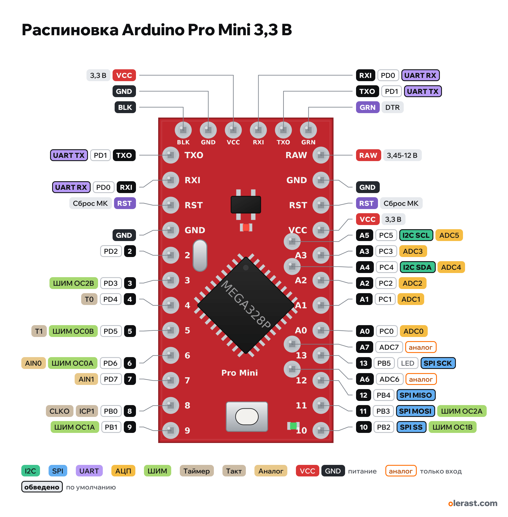
Arduino Pro Mini 3.3 V / 8 MHz pinout
Arduino Pro Mini 3.3 V / 8 MHz, ATmega328P, 3.3 V logic, 17.78×33.02 mm, 34 pins
verified15.10.2026
Top view, FTDI connector at the top.
BuyCompareDownload PNG- Chip
- ATmega328P
- Logic
- 3.3 V
- Power
- RAW 3.45-12 VVCC 3.3-3.3 VVCC on the FTDI connector
- Defaults in Arduino AVR core
- I2C: SDA 18, SCL 19SPI: MOSI 11, MISO 12, SCK 13, SS 10UART: TX 1, RX 0LED: 13
Which Arduino Pro Mini 3.3 V / 8 MHz pins are safe to use
Free to use
D0-D12, A0-A5
Use with care
- D13: onboard LED.
- A6, A7: analog input only.
Important
- 3.3 V / 8 MHz version: 3.3 V logic, do not apply 5 V to the pins. In the Arduino IDE choose the processor "ATmega328P (3.3V, 8 MHz)".
- Coordinates follow the SparkFun design. On clones (usually blue) A4–A7 are placed differently: at least four different board variants.
- A4 (SDA) and A5 (SCL) are brought out inside the board, not at the edge.
- A6 and A7 are analog inputs only.
- PWM isn't marked on the SparkFun version of the board; PWM: 3, 5, 6, 9, 10, 11.
- No USB on the board: flash through a USB-UART adapter (FTDI, CH340, CP2102) in the 6-pin connector.
Revisions and clones
- Clones: blue solder mask, different order or position of A4–A7, sometimes a different regulator (not MIC5205).
- SparkFun made 3.3 V / 8 MHz and 5 V / 16 MHz versions on the same board; tell them apart by the regulator, the resonator and the label on the back.
All pins
| Label | Number | Functions | Limits | Check |
|---|---|---|---|---|
| BLK | Ground | verifiedBlack wire of the FTDI cable, ground (CTS on the cable). | ||
| GND | Ground | verified | ||
| VCC | 3.3 V | power inputpower output | verified | |
| RXI | PD0, Arduino 0 | UART RX (RXD)PCINT (pin change interrupt) | verifiedConnected to the board's USB-UART through a resistor: keep it free when flashing and using Serial.Current per pin: up to 20 mA operating, 40 mA limit, less for the whole port (datasheet, Absolute Maximum Ratings).Board input: the adapter's TX goes here. | |
| TXO | PD1, Arduino 1 | UART TX (TXD)PCINT (pin change interrupt) | verifiedConnected to the board's USB-UART through a resistor: keep it free when flashing and using Serial.Current per pin: up to 20 mA operating, 40 mA limit, less for the whole port (datasheet, Absolute Maximum Ratings).Board output: the adapter's RX goes here. | |
| GRN | DTR: auto-reset when flashing | verifiedThrough a 0.1 µF capacitor to RESET: an adapter with DTR resets the board before flashing. | ||
| TXO | PD1, Arduino 1 | UART TX (TXD)PCINT (pin change interrupt) | verifiedConnected to the board's USB-UART through a resistor: keep it free when flashing and using Serial.Current per pin: up to 20 mA operating, 40 mA limit, less for the whole port (datasheet, Absolute Maximum Ratings). | |
| RXI | PD0, Arduino 0 | UART RX (RXD)PCINT (pin change interrupt) | verifiedConnected to the board's USB-UART through a resistor: keep it free when flashing and using Serial.Current per pin: up to 20 mA operating, 40 mA limit, less for the whole port (datasheet, Absolute Maximum Ratings). | |
| RST | MCU reset (low = reset) | verified | ||
| GND | Ground | verified | ||
| 2 | PD2, Arduino 2 | INT0 (attachInterrupt 0)PCINT (pin change interrupt) | verifiedCurrent per pin: up to 20 mA operating, 40 mA limit, less for the whole port (datasheet, Absolute Maximum Ratings). | |
| 3 | PD3, Arduino 3 | PWM OC2B (Timer2)INT1 (attachInterrupt 1)PCINT (pin change interrupt) | verifiedCurrent per pin: up to 20 mA operating, 40 mA limit, less for the whole port (datasheet, Absolute Maximum Ratings). | |
| 4 | PD4, Arduino 4 | T0 (Timer0 counter input)PCINT (pin change interrupt) | verifiedCurrent per pin: up to 20 mA operating, 40 mA limit, less for the whole port (datasheet, Absolute Maximum Ratings). | |
| 5 | PD5, Arduino 5 | PWM OC0B (Timer0, ~980 Hz)T1 (Timer1 counter input)PCINT (pin change interrupt) | verifiedCurrent per pin: up to 20 mA operating, 40 mA limit, less for the whole port (datasheet, Absolute Maximum Ratings). | |
| 6 | PD6, Arduino 6 | PWM OC0A (Timer0, ~980 Hz)AIN0 (comparator +)PCINT (pin change interrupt) | verifiedCurrent per pin: up to 20 mA operating, 40 mA limit, less for the whole port (datasheet, Absolute Maximum Ratings). | |
| 7 | PD7, Arduino 7 | AIN1 (comparator −)PCINT (pin change interrupt) | verifiedCurrent per pin: up to 20 mA operating, 40 mA limit, less for the whole port (datasheet, Absolute Maximum Ratings). | |
| 8 | PB0, Arduino 8 | ICP1 (Timer1 capture)CLKOPCINT (pin change interrupt) | verifiedCurrent per pin: up to 20 mA operating, 40 mA limit, less for the whole port (datasheet, Absolute Maximum Ratings). | |
| 9 | PB1, Arduino 9 | PWM OC1A (Timer1)PCINT (pin change interrupt) | verifiedCurrent per pin: up to 20 mA operating, 40 mA limit, less for the whole port (datasheet, Absolute Maximum Ratings). | |
| RAW | 9 V | power input | verifiedMIC5205 regulator input (150 mA). | |
| GND | Ground | verified | ||
| RST | MCU reset (low = reset) | verified | ||
| VCC | 3.3 V | power inputpower output | verifiedRegulated 3.3 V: regulator output or a supply input that bypasses it. | |
| A3 | PC3, Arduino A3 (17) | ADC3PCINT (pin change interrupt) | verifiedCurrent per pin: up to 20 mA operating, 40 mA limit, less for the whole port (datasheet, Absolute Maximum Ratings). | |
| A2 | PC2, Arduino A2 (16) | ADC2PCINT (pin change interrupt) | verifiedCurrent per pin: up to 20 mA operating, 40 mA limit, less for the whole port (datasheet, Absolute Maximum Ratings). | |
| A1 | PC1, Arduino A1 (15) | ADC1PCINT (pin change interrupt) | verifiedCurrent per pin: up to 20 mA operating, 40 mA limit, less for the whole port (datasheet, Absolute Maximum Ratings). | |
| A0 | PC0, Arduino A0 (14) | ADC0PCINT (pin change interrupt) | verifiedCurrent per pin: up to 20 mA operating, 40 mA limit, less for the whole port (datasheet, Absolute Maximum Ratings). | |
| 13 | PB5, Arduino 13 | SPI SCKPCINT (pin change interrupt) | onboard LED | verifiedCurrent per pin: up to 20 mA operating, 40 mA limit, less for the whole port (datasheet, Absolute Maximum Ratings).Green LED through 330 Ω. |
| 12 | PB4, Arduino 12 | SPI MISOPCINT (pin change interrupt) | verifiedCurrent per pin: up to 20 mA operating, 40 mA limit, less for the whole port (datasheet, Absolute Maximum Ratings). | |
| 11 | PB3, Arduino 11 | PWM OC2A (Timer2)SPI MOSIPCINT (pin change interrupt) | verifiedCurrent per pin: up to 20 mA operating, 40 mA limit, less for the whole port (datasheet, Absolute Maximum Ratings). | |
| 10 | PB2, Arduino 10 | PWM OC1B (Timer1)SPI SSPCINT (pin change interrupt) | verifiedCurrent per pin: up to 20 mA operating, 40 mA limit, less for the whole port (datasheet, Absolute Maximum Ratings). | |
| A5 | PC5, Arduino A5 (19) | ADC5I2C SCLPCINT (pin change interrupt) | verifiedCurrent per pin: up to 20 mA operating, 40 mA limit, less for the whole port (datasheet, Absolute Maximum Ratings).Labeled on the back. On clones the A4/A5 position differs. | |
| A4 | PC4, Arduino A4 (18) | ADC4I2C SDAPCINT (pin change interrupt) | verifiedCurrent per pin: up to 20 mA operating, 40 mA limit, less for the whole port (datasheet, Absolute Maximum Ratings).Labeled on the back. On clones the A4/A5 position differs. | |
| A7 | ADC7, Arduino A7 (21) | ADC7 | analog input only | verifiedAnalog input only: digitalRead/digitalWrite and pull-up don't work (ATmega328P in TQFP/QFN package only).Labeled on the back. On clones the A6/A7 position differs. |
| A6 | ADC6, Arduino A6 (20) | ADC6 | analog input only | verifiedAnalog input only: digitalRead/digitalWrite and pull-up don't work (ATmega328P in TQFP/QFN package only).Labeled on the back. On clones the A6/A7 position differs. |
Sources
Every pin is verified against the manufacturer's documents.
- SparkFun Arduino Pro Mini 328: Hardware/Arduino-Pro-Mini.brd (GitHub, master bcf8de441f)board drawing, checked 15.10.2026size 17.78×33.02 mm, pad centers of all rows, FTDI and internal A4–A7, components, silkscreen labels
- Softsolder: Arduino Pro Mini pin coordinatesthird-party source, checked 15.10.2026pin coordinates match Eagle within ±0.05 mm
- ATmega328P Datasheet (Microchip DS40002061)datasheet, checked 15.10.2026alternate functions of ports B, C, D: OC0A/B, OC1A/B, OC2A/B, INT0/1, PCINT, SPI, TWI, USART, ADC0–7, AIN0/1; ADC6/7 analog only; pin currents
- ArduinoCore-avr: variants/standard/pins_arduino.hArduino core, checked 15.10.2026Arduino numbers ↔ ports, PWM on 3, 5, 6, 9, 10, 11, SS 10, MOSI 11, MISO 12, SCK 13, SDA A4, SCL A5, LED_BUILTIN 13
Size: from the SparkFun Eagle file (0.7×1.3 in).
FAQ
- Which Arduino Pro Mini 3.3 V / 8 MHz pins are I2C, SPI and UART?
- By default in Arduino AVR core: I2C: SDA A4, SCL A5; SPI: MOSI D11, MISO D12, SCK D13, SS D10; UART: TX D1, RX D0.
- Which pin is the Arduino Pro Mini 3.3 V / 8 MHz LED on?
- LED on D13 (green).
- Are the Arduino Pro Mini 3.3 V / 8 MHz pins 5 V tolerant?
- No. The logic is 3.3 V and the pins are not 5 V tolerant: use a divider or a level shifter for 5 V signals.
You might also need
Schematic with this board
schematic builder with the board already placed
Flash this board
upload a sketch or .bin to this board from the browser
Power budget
will the regulator cope and how long the battery lasts
Calculators
LED resistor, voltage divider, battery runtime, 3D print cost, LED strip power supply and pF, nF, µF conversion
Similar boards
Next
Need firmware or a device built on Arduino? I'll build it to order