Boost module 0.9–5 V → 5 V with a USB socket pinout
Boost module 0.9–5 V → 5 V with a USB socket (600 mA), unmarked (boost controller, SOT-23), 5 V logic, 25×18 mm, 4 pins
partly verified17.10.2026
Top view, input on the left, USB-A socket on the right.
Download PNG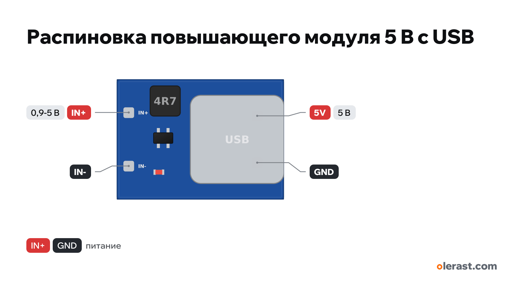
- Chip
- unmarked (boost controller, SOT-23)
- Logic
- 5 V
- Power
- IN+ 0.9-5 V
Important
- For powering a 5 V board from 1–2 AA batteries or one Li-ion cell through a USB cable.
- Output current depends on the input: up to 600 mA from 2×AA, about 200 mA from one AA. An ESP32 with Wi-Fi will not run from one AA.
- The LED is always on: a few mA with no load, so batteries drain even while asleep.
- A boost converter does not step down: do not feed more than 5 V to the input.
Revisions and clones
- 3.3 V boost modules are not sold in bulk: for 3.3 V from 1–2 AA use the Pololu U1V11F3 or similar (the manufacturer has documentation).
All pins
| Label | Number | Functions | Limits | Check |
|---|---|---|---|---|
| IN+ | 3 V | power input | not verifiedThe seller's description has no photo of the labels and no drawing: the position of IN+/IN− and the socket pins is approximate, the chip is not named. Read the labels on the board.Input 0.9–5 V. | |
| IN- | Ground | not verifiedThe seller's description has no photo of the labels and no drawing: the position of IN+/IN− and the socket pins is approximate, the chip is not named. Read the labels on the board.Input negative, tied to the USB socket negative. | ||
| 5V | 5 V | power output | not verifiedThe seller's description has no photo of the labels and no drawing: the position of IN+/IN− and the socket pins is approximate, the chip is not named. Read the labels on the board.Pin 1 of the USB-A socket. There is no separate pad: solder the wire to the socket pin or use a USB cable.Labelled on other revisions as: VBUS, USB 5V | |
| GND | Ground | not verifiedThe seller's description has no photo of the labels and no drawing: the position of IN+/IN− and the socket pins is approximate, the chip is not named. Read the labels on the board.Pin 4 of the USB-A socket. |
Sources
Not verified against the manufacturer: 4 of 4 pins. The pin card says what confirms each one and where sources disagree.
- Robu: DC-DC Boost Module (0.9V~5V) to 5V 600mA USB Step-up Boardthird-party source, checked 17.10.2026IN+ and IN− input, USB socket output, 18×25 mm, from 2×AA 500–600 mA, from one AA about 200 mA, LED
Size: 25×18 mm per Robu; coordinates not dimensioned (approximate).
You might also need
Similar boards
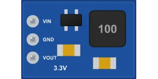
DD4012SA mini buck module, 3.3 V (up to 1 A, 3 pins)
unmarked (controller in SOT-23-6)3 pins
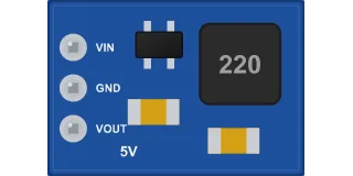
DD4012SA mini buck module for 5 V (up to 1 A, 3 pins)
unmarked (controller in SOT-23-6)3 pins
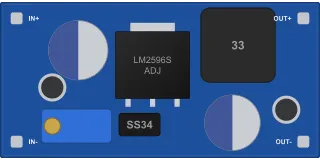
LM2596 buck module (blue 43×21, trimmer, up to 2-3 A)
LM2596S-ADJ4 pins
MP1584EN mini step-down module (22×17, 1.5–3 A)
MP1584EN4 pins