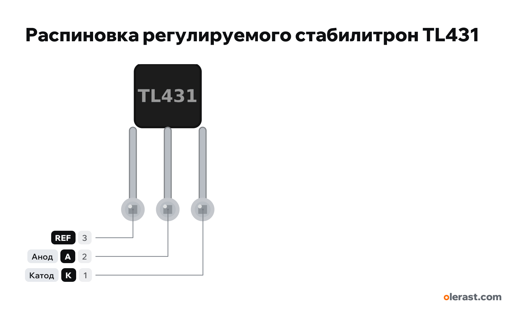
TL431 adjustable shunt regulator pinout
TL431 adjustable shunt regulator (TO-92), TL431, 5 V logic, 7.2×11.5 mm, 3 pins
verified20.10.2026
View of the flat marked side, pins down: REF, A, K left to right (TI numbers right to left: K 1, A 2, REF 3).
Download PNG- Chip
- TL431
- Logic
- 5 V
Important
- Output: Vout = 2.495 × (1 + R1/R2). R1 between K and REF, R2 between REF and A. With R1 = R2 = 10 kΩ the output is 4.99 V.
- Cathode from 2.495 to 36 V, cathode current 1-100 mA. Size the resistor from the positive rail to the cathode for the load current plus 1 mA for the TL431 itself.
- For ESP32 and Arduino: 2.5 V reference for the ADC (tie REF to K) or a battery voltage threshold detector. Feed the output to a GPIO only if it is below 3.3 V (ESP32) or 5 V (Arduino).
- Choose the cathode capacitance from the stability graph in the TI datasheet: at some values the TL431 oscillates.
- TI and onsemi number the pins differently (1 K at TI, 1 REF at onsemi), but the layout is the same: look at the flat side, REF on the left.
- Powered through a resistor from the source to the cathode: R = (Vin − Vout) / Ik, Ik from 1 to 100 mA.
Revisions and clones
- SOT-23-3 at TI (TL431xDBZ): 1 K, 2 REF, 3 A; TL432 in SOT-23-3: 1 REF, 2 K, 3 A. For SMD versions from other makers check the pin order in the datasheet.
- SOT-89 at TI (PK): 1 REF, 2 A (and tab), 3 K.
- TL432: same die, different pin order.
All pins
| Label | Number | Functions | Limits | Check |
|---|---|---|---|---|
| REF | pin 3 | REF: midpoint of the R1/R2 divider, 2.495 V | verifiedLabelled on other revisions as: R, Reference, 3 | |
| A | pin 2 | Anode: to GND | verifiedLabelled on other revisions as: ANODE, anode, 2 | |
| K | pin 1 | Cathode: stabilized voltage output, through a resistor to positive | verifiedLabelled on other revisions as: CATHODE, cathode, 1 |
Sources
Every pin is verified against the manufacturer's documents.
- TI TL431, TL432 Precision Programmable Reference (SLVS543S, May 2024)datasheet, checked 20.10.2026LP (TO-92), top view: 1 CATHODE, 2 ANODE, 3 REF, flat side on the right; Vref 2495 mV (TL431: 2440-2550); VKA from Vref to 36 V; IKA 1-100 mA; DBZ (SOT-23-3): 1 CATHODE, 2 REF, 3 ANODE; TL432 DBZ: 1 REF, 2 CATHODE, 3 ANODE; PK (SOT-89): 1 REF, 2 ANODE, 3 CATHODE
- onsemi TL431, A, B Series Programmable Precision References (Rev. 45, November 2025)datasheet, checked 20.10.2026TO-92: Pin 1 Reference, 2 Anode, 3 Cathode; cathode up to 36 V, current 1-100 mA
Size: TO-92 package 4.8×4.6 mm, leads spread to 2.54 mm pitch (the package pitch is 1.27 mm) (approximate).