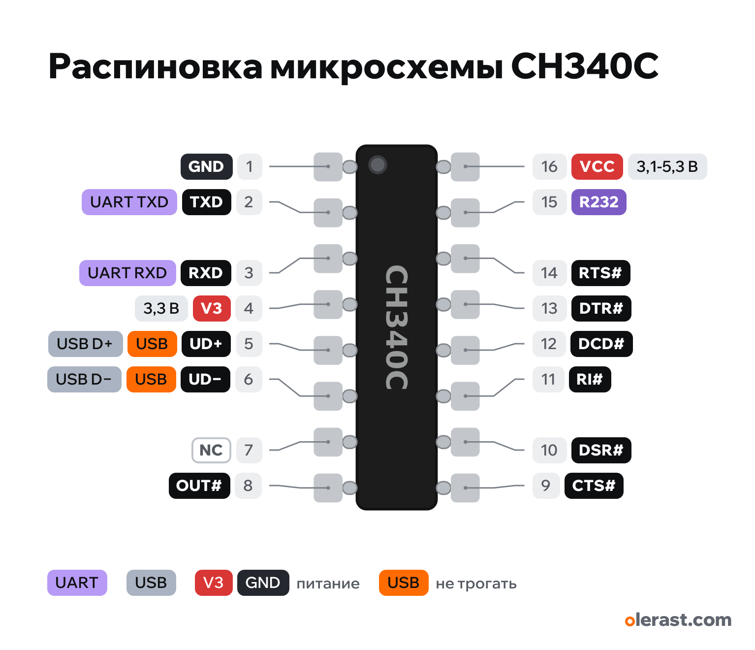
CH340C chip pinout
CH340C chip (SOP-16), USB-UART bridge without a crystal, CH340C, 5 V logic, 20.32×9.6 mm, 16 pins
verified20.10.2026
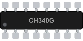
Top view, notch (dot) at the bottom left: pins 1–8 along the bottom left to right, 9–16 along the top right to left (16 above 1), rotated 90° on the diagram.
Download PNG- Chip
- CH340C
- Logic
- 5 V
- Power
- VCC (pin 16) 3.1-5.3 V
Important
- The CH340C works without a crystal: leave pin 7 unconnected. Baud rate accuracy is about 1.2 % (0.3 % on the CH340G with a crystal).
- 5 V supply: VCC (16) to USB 5 V, V3 (4) through 0.1 µF to ground, TXD and RXD at 5 V level. 3.3 V supply: VCC and V3 together to 3.3 V, 3.3 V levels.
- TXD (2) goes to the microcontroller's RX, RXD (3) to its TX: the lines cross.
- Arduino auto-reset: DTR# (13) through 0.1 µF to RESET. ESP32 and ESP8266 need a two-transistor circuit to EN and GPIO0, driven by DTR# and RTS#.
- Driver: on Windows 10 and 11 it usually installs itself; if there is no port, get the CH341SER driver from the WCH site. A charge-only cable won't give a port at all.
- Runs from 5 V (5 V logic) or from 3.3 V (3.3 V logic): the level of TXD, RXD and the modem signals equals the supply.
- Operating current 7 mA typ., up to 20 mA; in USB suspend 0.05–0.2 mA.
Revisions and clones
- CH340G: same package and pin order, needs a 12 MHz crystal on pins 7 and 8.
- CH340B (SOP-16): no crystal, pin 7 is RST#, pin 8 is not connected, has an EEPROM for the serial number.
- CH340N (SOP-8), CH340E and CH340X (MSOP-10), CH340K (ESSOP-10): different pin order, see the WCH datasheet.
All pins
| Label | Number | Functions | Limits | Check |
|---|---|---|---|---|
| GND | pin 1 | Ground | verifiedLabelled on other revisions as: 1 | |
| TXD | pin 2 | UART TXD: output, to the microcontroller's RX | verifiedLabelled on other revisions as: TX, 2 | |
| RXD | pin 3 | UART RXD: input, from the microcontroller's TX | verifiedInput no higher than VCC + 0.5 V: when the CH340 is powered from 3.3 V, feed a 5 V signal through a divider.Labelled on other revisions as: RX, 3 | |
| V3 | pin 4 | 3.3 V | power inputpower output | verifiedAt 5 V supply: 0.1 µF capacitor to ground (internal 3.3 V regulator for USB). At 3.3 V supply: connect to VCC. Don't load this pin.Labelled on other revisions as: 4 |
| UD+ | pin 5 | USB D+ | USB line | verifiedDirectly to D+ of the connector, no resistors: the USB pull-up is internal.Labelled on other revisions as: D+, 5 |
| UD− | pin 6 | USB D− | USB line | verifiedLabelled on other revisions as: UD-, D-, 6 |
| NC | pin 7 | not connected | verifiedNot connected on the CH340C: the oscillator is inside. Leave it unconnected.Labelled on other revisions as: 7 | |
| OUT# | pin 8 | OUT#: modem output, active low | verifiedOn CH340C batches whose number has 4 and the last digits above B40: with a 4.7 kΩ resistor to ground it becomes a second DTR# (open drain, for loading an MCU).Labelled on other revisions as: 8 | |
| CTS# | pin 9 | CTS#: modem input, active low | verifiedLabelled on other revisions as: CTS, 9 | |
| DSR# | pin 10 | DSR#: modem input, active low | verifiedLabelled on other revisions as: DSR, 10 | |
| RI# | pin 11 | RI#: modem input, active low | verifiedLabelled on other revisions as: RI, 11 | |
| DCD# | pin 12 | DCD#: modem input, active low | verifiedLabelled on other revisions as: DCD, 12 | |
| DTR# | pin 13 | DTR#: modem output, active low; Arduino auto-reset through 0.1 µF to RESET | verifiedArduino: DTR# through a 0.1 µF capacitor to RESET (auto-reset before flashing). ESP32 and ESP8266: DTR# and RTS# through two transistors to EN and GPIO0.Labelled on other revisions as: DTR, 13 | |
| RTS# | pin 14 | RTS#: modem output, active low | verifiedLabelled on other revisions as: RTS, 14 | |
| R232 | pin 15 | R232: HIGH inverts RXD for RS232, built-in pull-down | verifiedLeave unconnected for UART: internal pull-down.Labelled on other revisions as: 15 | |
| VCC | pin 16 | 5 V | power input | verified0.1 µF ceramic to GND at the pin.Labelled on other revisions as: 16 |
Sources
Every pin is verified against the manufacturer's documents.
- WCH CH340 Datasheet (I), version 3B (SparkFun copy)datasheet, checked 20.10.2026SOP-16 on CH340G, CH340C, CH340B: 1 GND, 2 TXD, 3 RXD, 4 V3, 5 UD+, 6 UD−, 7 XI (G) or NC (C), 8 XO (G) or OUT# (C), 9 CTS#, 10 DSR#, 11 RI#, 12 DCD#, 13 DTR#, 14 RTS#, 15 R232, 16 VCC; at 5 V, V3 through 0.1 µF to ground, at 3.3 V connect V3 to VCC; VCC 4.0–5.3 V (5 V) or 2.9–3.6 V (CH340G, 3.3 V), 3.1–3.6 V (CH340C); current up to 20 mA; VIH 2.3 V at 5 V; input up to VCC + 0.5 V; the CH340G needs a 12 MHz crystal, the CH340C has a built-in oscillator; UD+ and UD− without series resistors
- SparkFun: How to Install CH340 Driversthird-party source, checked 20.10.2026CH340 driver for Windows, macOS, Linux; usually installs itself on Windows 10 and 11
Size: drawn twice as large: the real SOP-16 is 10×3.9 mm, 1.27 mm pitch, 6 mm wide including leads (approximate).