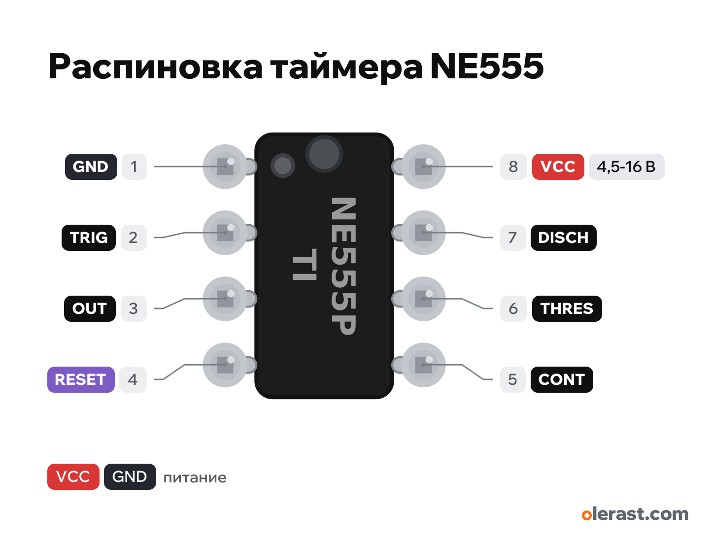
NE555 timer pinout
NE555 timer (DIP-8), NE555, 5 V logic, 10.7×9.7 mm, 8 pins
verified20.10.2026
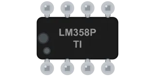
Top view, notch on the left: pins 1-4 at the bottom from left to right, 5-8 at the top from right to left (8 above 1), rotated 90° on the diagram.
Download PNG- Chip
- NE555
- Logic
- 5 V
- Power
- VCC (pin 8) 4.5-16 V
Important
- The NE555 needs 4.5 V: it will not start from the 3.3 V of an ESP32 or Pico. For 3.3 V use a CMOS version with the same pinout: TLC555 (from 2 V) or ICM7555 (2-18 V). The TLC555 output delivers about 10 mA to a load.
- TI wiring: 0.1 µF ceramic between VCC (8) and GND (1) at the package, 10 nF from CONT (5) to GND, RESET (4) to VCC.
- With a 5-12 V supply, feed the NE555 output to an ESP32 input only through a divider or transistor: GPIO tolerates up to 3.6 V.
- Loads above 200 mA (motor, 12 V relay with higher coil current) go through a transistor or MOSFET. Put a diode across the relay coil, cathode to positive.
- Oscillator: f = 1.44 / ((RA + 2·RB) · C). Per TI, RA + RB is up to 3.4 MΩ at 5 V and up to 10 MΩ at 15 V.
- Draws 3 mA at 5 V and 10 mA at 15 V with no load (TI).
Revisions and clones
- SOIC-8 (NE555D): same pin order 1-8, package for soldering to a board.
- NE556: two timers in DIP-14, different pinout.
- Russian-made equivalent of the KR1006VI1 in DIP-8 with the same pinout.
All pins
| Label | Number | Functions | Limits | Check |
|---|---|---|---|---|
| GND | pin 1 | Ground | verifiedLabelled on other revisions as: 1 | |
| TRIG | pin 2 | TRIG: below 1/3 VCC starts timing, output HIGH | verifiedLabelled on other revisions as: TRIGGER, 2 | |
| OUT | pin 3 | OUT: timer output, up to 200 mA | verifiedThe output sources and sinks up to 200 mA. At 5 V and 100 mA, HIGH is about 3.3 V (TI).Labelled on other revisions as: OUTPUT, 3 | |
| RESET | pin 4 | RESET: LOW resets the timer, output LOW | verifiedUnused: tie to VCC. A floating pin causes false resets.Labelled on other revisions as: 4 | |
| CONT | pin 5 | CONT: 2/3 VCC threshold, can be shifted with a voltage | verifiedUnused: 10 nF (0.01 µF) capacitor to GND, as in typical TI circuits.Labelled on other revisions as: CONTROL, CV, 5 | |
| THRES | pin 6 | THRES: above 2/3 VCC ends timing, output LOW | verifiedLabelled on other revisions as: THRESHOLD, THR, 6 | |
| DISCH | pin 7 | DISCH: open collector, discharges the timing capacitor | verifiedLabelled on other revisions as: DISCHARGE, DIS, 7 | |
| VCC | pin 8 | 5 V | power input | verifiedLabelled on other revisions as: V+, 8 |
Sources
Every pin is verified against the manufacturer's documents.
- TI NA555, NE555, SA555, SE555 Precision Timers (SLFS022K, March 2026)datasheet, checked 20.10.2026P (PDIP-8), top view: 1 GND, 2 TRIG, 3 OUT, 4 RESET, 5 CONT, 6 THRES, 7 DISCH, 8 VCC; NE555: VCC 4.5-16 V, output ±200 mA; no-load supply current 3 mA at 5 V, 10 mA at 15 V; output HIGH about 3.3 V at 5 V and 100 mA; CONT in typical circuits 0.01 µF to GND; 0.1 µF ceramic between VCC and GND
- TI TLC555 CMOS Timer (SLFS043K, January 2026)datasheet, checked 20.10.2026same pinout as the NE555; TLC555C from 2 to 15 V; output: sink current 100 mA, source current 10 mA (typical)
- Renesas ICM7555, ICM7556 General Purpose Timers (FN2867 Rev.10.01)datasheet, checked 20.10.2026CMOS timer, 2-18 V supply
Size: PDIP-8 package about 9.8×6.35 mm, pitch 2.54, rows 7.62 apart; package drawn narrower so the pins are visible (approximate).