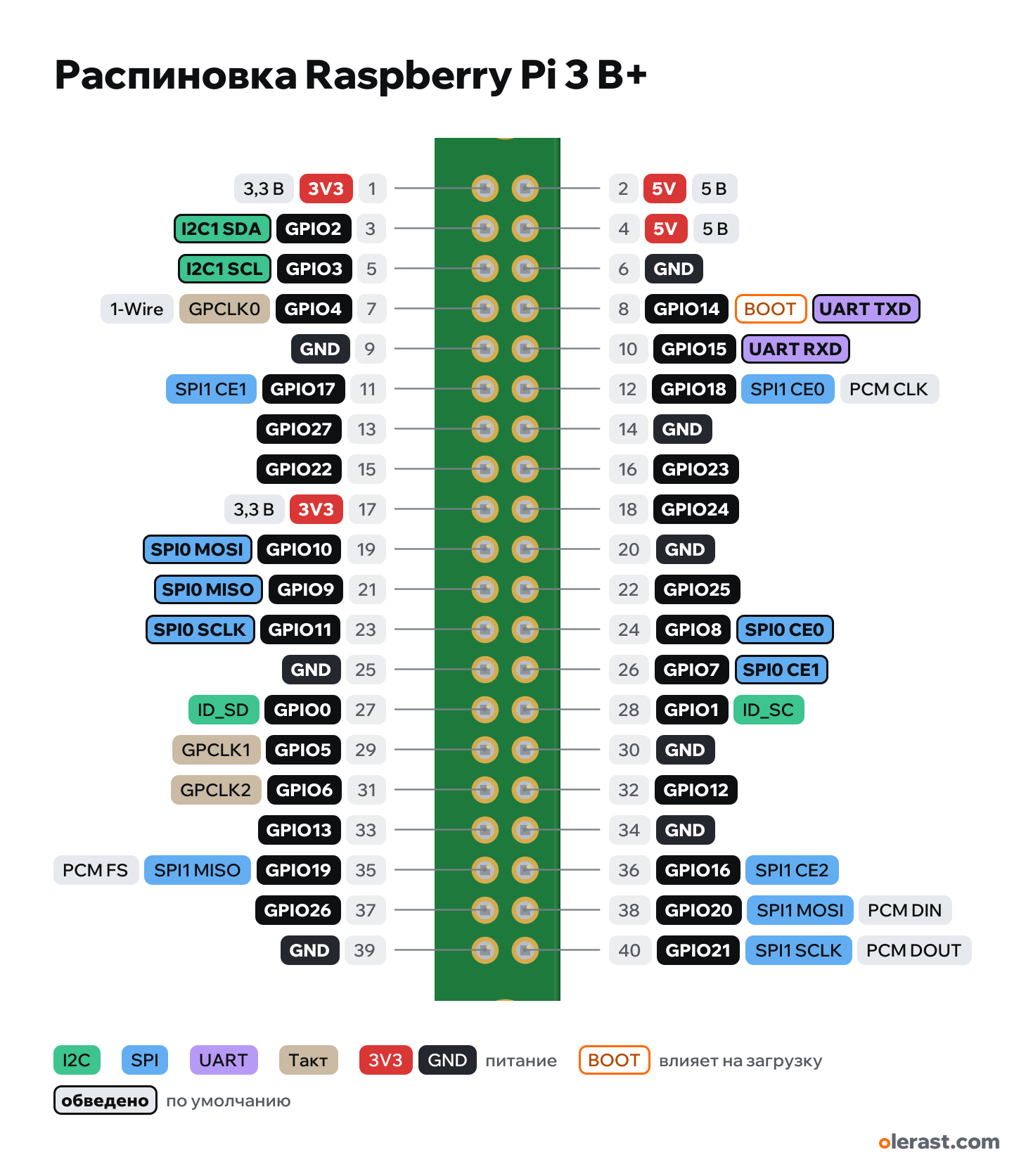
Raspberry Pi 3 B+ pinout
Raspberry Pi 3 Model B+, BCM2837B0, 3.3 V logic, 85×56 mm, 40 pins
verified17.10.2026
Top view, GPIO header at the top edge, pin 1 on the left, rotated 90° on the diagram.
CompareDownload PNG- Chip
- BCM2837B0
- Logic
- 3.3 V
- Power
- Micro-USB 4.75-5.25 V5V on GPIO 4.75-5.25 V
- Defaults in Raspberry Pi OS (default in config.txt / dtoverlay)
- I2C: SDA 2, SCL 3SPI: MOSI 10, MISO 9, SCK 11, SS 8UART: TX 14, RX 15
Which Raspberry Pi 3 B+ pins are safe to use
Free to use
GPIO0, GPIO1, GPIO4-13, GPIO15-27
Use with care
- GPIO2, GPIO3: onboard pull-up or divider.
- GPIO14: signal at boot.
Important
- 3.3 V logic. Do not apply 5 V to a GPIO: the pins do not tolerate 5 V and the whole board can burn out. For 5 V sensors use a divider or a level shifter.
- In programs, numbering is by BCM (GPIO17), not by pin number (11). The board has no pin labels, only the number 1 at the first pin.
- Current: the pins are rated for 16 mA, while the whole 3.3 V rail on the GPIO is good for about 3 mA per pin on average (Raspberry Pi documentation). Relays, motors and strips only through a transistor and from a separate supply.
- Default buses: I2C1 on GPIO2/3 (pins 3/5, with 1.8 kΩ pull-ups), SPI0 on GPIO10/9/11, CE0 8, CE1 7, UART on GPIO14/15. Enable them in raspi-config or config.txt.
- No analog inputs: for an ADC you need an external module (ADS1115, MCP3008).
- Hardware PWM: GPIO12, 13, 18, 19 (two channels). I2S (PCM) audio: GPIO18–21.
- Bluetooth takes the main UART: GPIO14/15 uses the mini UART by default. dtoverlay=disable-bt restores the full one.
- Power supply: 5 V 2.5 A, up to 1.2 A in total for USB devices.
All pins
| Label | Number | Functions | Limits | Check |
|---|---|---|---|---|
| 5V | pin 2 | 5 V | power inputpower output | verified5 V straight from the power supply (after protection). You can also power the board through this pin, but this bypasses reverse polarity protection. |
| 5V | pin 4 | 5 V | power inputpower output | verified5 V straight from the power supply (after protection). You can also power the board through this pin, but this bypasses reverse polarity protection. |
| GND | pin 6 | Ground | verified | |
| GPIO14 | GPIO14, pin 8 | interrupt (edge, via gpiod)software PWMUART TXD (console, if enabled) | not 5 V tolerantoutputs a signal at boot | verifiedWith the console enabled (enable_uart=1) the boot log goes here.3.3 V input and output, not 5 V tolerant: from 5 V modules, only through a divider or a level shifter.Labelled on other revisions as: BCM 14 |
| GPIO15 | GPIO15, pin 10 | interrupt (edge, via gpiod)software PWMUART RXD (console, if enabled) | not 5 V tolerant | verified3.3 V input and output, not 5 V tolerant: from 5 V modules, only through a divider or a level shifter.Labelled on other revisions as: BCM 15 |
| GPIO18 | GPIO18, pin 12 | interrupt (edge, via gpiod)PWM0PCM CLK (I2S)SPI1 CE0 | not 5 V tolerant | verified3.3 V input and output, not 5 V tolerant: from 5 V modules, only through a divider or a level shifter.Labelled on other revisions as: BCM 18 |
| GND | pin 14 | Ground | verified | |
| GPIO23 | GPIO23, pin 16 | interrupt (edge, via gpiod)software PWM | not 5 V tolerant | verified3.3 V input and output, not 5 V tolerant: from 5 V modules, only through a divider or a level shifter.Labelled on other revisions as: BCM 23 |
| GPIO24 | GPIO24, pin 18 | interrupt (edge, via gpiod)software PWM | not 5 V tolerant | verified3.3 V input and output, not 5 V tolerant: from 5 V modules, only through a divider or a level shifter.Labelled on other revisions as: BCM 24 |
| GND | pin 20 | Ground | verified | |
| GPIO25 | GPIO25, pin 22 | interrupt (edge, via gpiod)software PWM | not 5 V tolerant | verified3.3 V input and output, not 5 V tolerant: from 5 V modules, only through a divider or a level shifter.Labelled on other revisions as: BCM 25 |
| GPIO8 | GPIO8, pin 24 | interrupt (edge, via gpiod)software PWMSPI0 CE0 | not 5 V tolerant | verified3.3 V input and output, not 5 V tolerant: from 5 V modules, only through a divider or a level shifter.Labelled on other revisions as: BCM 8 |
| GPIO7 | GPIO7, pin 26 | interrupt (edge, via gpiod)software PWMSPI0 CE1 | not 5 V tolerant | verified3.3 V input and output, not 5 V tolerant: from 5 V modules, only through a divider or a level shifter.Labelled on other revisions as: BCM 7 |
| GPIO1 | GPIO1, pin 28 | interrupt (edge, via gpiod)software PWMID_SC (I2C0 SCL) — EEPROM HAT | not 5 V tolerant | verifiedReserved for the HAT expansion board EEPROM: do not use if you have a HAT with an EEPROM.3.3 V input and output, not 5 V tolerant: from 5 V modules, only through a divider or a level shifter.Labelled on other revisions as: BCM 1 |
| GND | pin 30 | Ground | verified | |
| GPIO12 | GPIO12, pin 32 | interrupt (edge, via gpiod)PWM0 | not 5 V tolerant | verified3.3 V input and output, not 5 V tolerant: from 5 V modules, only through a divider or a level shifter.Labelled on other revisions as: BCM 12 |
| GND | pin 34 | Ground | verified | |
| GPIO16 | GPIO16, pin 36 | interrupt (edge, via gpiod)software PWMSPI1 CE2 | not 5 V tolerant | verified3.3 V input and output, not 5 V tolerant: from 5 V modules, only through a divider or a level shifter.Labelled on other revisions as: BCM 16 |
| GPIO20 | GPIO20, pin 38 | interrupt (edge, via gpiod)software PWMPCM DIN (I2S)SPI1 MOSI | not 5 V tolerant | verified3.3 V input and output, not 5 V tolerant: from 5 V modules, only through a divider or a level shifter.Labelled on other revisions as: BCM 20 |
| GPIO21 | GPIO21, pin 40 | interrupt (edge, via gpiod)software PWMPCM DOUT (I2S)SPI1 SCLK | not 5 V tolerant | verified3.3 V input and output, not 5 V tolerant: from 5 V modules, only through a divider or a level shifter.Labelled on other revisions as: BCM 21 |
| 3V3 | pin 1 | 3.3 V | power output | verified3.3 V output of the board. Raspberry Pi does not specify the current; older boards budgeted about 50 mA for the whole header. |
| GPIO2 | GPIO2, pin 3 | interrupt (edge, via gpiod)software PWMI2C1 SDA | not 5 V tolerantonboard pull-up | verifiedThe board has a 1.8 kΩ pull-up to 3.3 V: it reads 1 as a regular input, fine for a button to GND, not suitable for a pull-down.3.3 V input and output, not 5 V tolerant: from 5 V modules, only through a divider or a level shifter.Labelled on other revisions as: BCM 2 |
| GPIO3 | GPIO3, pin 5 | interrupt (edge, via gpiod)software PWMI2C1 SCL | not 5 V tolerantonboard pull-up | verifiedThe board has a 1.8 kΩ pull-up to 3.3 V. Shorting to GND after shutdown turns the board on (except Zero).3.3 V input and output, not 5 V tolerant: from 5 V modules, only through a divider or a level shifter.Labelled on other revisions as: BCM 3 |
| GPIO4 | GPIO4, pin 7 | interrupt (edge, via gpiod)software PWMGPCLK01-Wire (dtoverlay=w1-gpio by default) | not 5 V tolerant | verified3.3 V input and output, not 5 V tolerant: from 5 V modules, only through a divider or a level shifter.Labelled on other revisions as: BCM 4 |
| GND | pin 9 | Ground | verified | |
| GPIO17 | GPIO17, pin 11 | interrupt (edge, via gpiod)software PWMSPI1 CE1 | not 5 V tolerant | verified3.3 V input and output, not 5 V tolerant: from 5 V modules, only through a divider or a level shifter.Labelled on other revisions as: BCM 17 |
| GPIO27 | GPIO27, pin 13 | interrupt (edge, via gpiod)software PWM | not 5 V tolerant | verified3.3 V input and output, not 5 V tolerant: from 5 V modules, only through a divider or a level shifter.Labelled on other revisions as: BCM 27 |
| GPIO22 | GPIO22, pin 15 | interrupt (edge, via gpiod)software PWM | not 5 V tolerant | verified3.3 V input and output, not 5 V tolerant: from 5 V modules, only through a divider or a level shifter.Labelled on other revisions as: BCM 22 |
| 3V3 | pin 17 | 3.3 V | power output | verified3.3 V output of the board. Raspberry Pi does not specify the current; older boards budgeted about 50 mA for the whole header. |
| GPIO10 | GPIO10, pin 19 | interrupt (edge, via gpiod)software PWMSPI0 MOSI | not 5 V tolerant | verified3.3 V input and output, not 5 V tolerant: from 5 V modules, only through a divider or a level shifter.Labelled on other revisions as: BCM 10 |
| GPIO9 | GPIO9, pin 21 | interrupt (edge, via gpiod)software PWMSPI0 MISO | not 5 V tolerant | verified3.3 V input and output, not 5 V tolerant: from 5 V modules, only through a divider or a level shifter.Labelled on other revisions as: BCM 9 |
| GPIO11 | GPIO11, pin 23 | interrupt (edge, via gpiod)software PWMSPI0 SCLK | not 5 V tolerant | verified3.3 V input and output, not 5 V tolerant: from 5 V modules, only through a divider or a level shifter.Labelled on other revisions as: BCM 11 |
| GND | pin 25 | Ground | verified | |
| GPIO0 | GPIO0, pin 27 | interrupt (edge, via gpiod)software PWMID_SD (I2C0 SDA) — EEPROM HAT | not 5 V tolerant | verifiedReserved for the HAT expansion board EEPROM: do not use if you have a HAT with an EEPROM.3.3 V input and output, not 5 V tolerant: from 5 V modules, only through a divider or a level shifter.Labelled on other revisions as: BCM 0 |
| GPIO5 | GPIO5, pin 29 | interrupt (edge, via gpiod)software PWMGPCLK1 | not 5 V tolerant | verified3.3 V input and output, not 5 V tolerant: from 5 V modules, only through a divider or a level shifter.Labelled on other revisions as: BCM 5 |
| GPIO6 | GPIO6, pin 31 | interrupt (edge, via gpiod)software PWMGPCLK2 | not 5 V tolerant | verified3.3 V input and output, not 5 V tolerant: from 5 V modules, only through a divider or a level shifter.Labelled on other revisions as: BCM 6 |
| GPIO13 | GPIO13, pin 33 | interrupt (edge, via gpiod)PWM1 | not 5 V tolerant | verified3.3 V input and output, not 5 V tolerant: from 5 V modules, only through a divider or a level shifter.Labelled on other revisions as: BCM 13 |
| GPIO19 | GPIO19, pin 35 | interrupt (edge, via gpiod)PWM1PCM FS (I2S)SPI1 MISO | not 5 V tolerant | verified3.3 V input and output, not 5 V tolerant: from 5 V modules, only through a divider or a level shifter.Labelled on other revisions as: BCM 19 |
| GPIO26 | GPIO26, pin 37 | interrupt (edge, via gpiod)software PWM | not 5 V tolerant | verified3.3 V input and output, not 5 V tolerant: from 5 V modules, only through a divider or a level shifter.Labelled on other revisions as: BCM 26 |
| GND | pin 39 | Ground | verified |
Sources
Every pin is verified against the manufacturer's documents.
- Raspberry Pi Documentation: GPIO and the 40-pin headeruser guide, checked 17.10.202640 pin functions (3V3, 5V, GND, GPIO by BCM), 3.3 V logic, output up to 16 mA per pin (4 mA by default on the 4 series, up to 8), GPIO2/3 pull-ups, ID_SD/ID_SC for the HAT EEPROM
- pinout.xyz (cross-check of alternate functions)third-party source, checked 17.10.2026I2C1 on 2/3, SPI0 on 7–11, SPI1 on 16–21, UART on 14/15, PWM on 12, 13, 18, 19, PCM on 18–21, GPCLK on 4–6
- Raspberry Pi 3 Model B+ mechanical drawingboard drawing, checked 17.10.2026board 85×56 mm, holes 58×49, GPIO header, positions of USB, Ethernet, HDMI, power and audio
Size: per the Raspberry Pi mechanical drawing.
FAQ
- Which Raspberry Pi 3 B+ pins are I2C, SPI and UART?
- By default in Raspberry Pi OS (default in config.txt / dtoverlay): I2C: SDA GPIO2, SCL GPIO3; SPI: MOSI GPIO10, MISO GPIO9, SCK GPIO11, SS GPIO8; UART: TX GPIO14, RX GPIO15.
- Are the Raspberry Pi 3 B+ pins 5 V tolerant?
- No. The logic is 3.3 V and the pins are not 5 V tolerant: use a divider or a level shifter for 5 V signals.
You might also need
Similar boards
Next
Need firmware or a device built on BCM2837B0? I'll build it to order