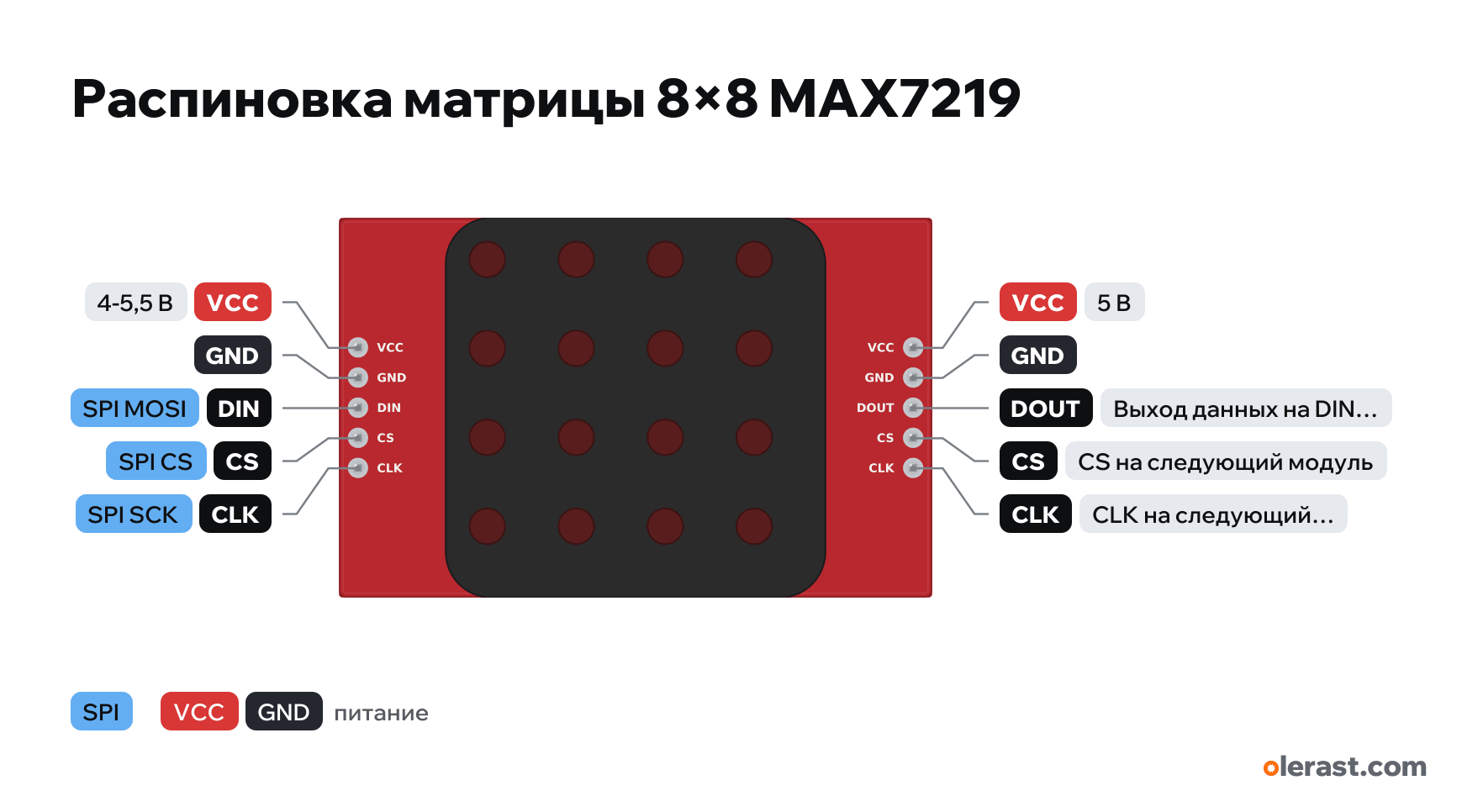
8×8 matrix on MAX7219 pinout
8×8 matrix on MAX7219 (input VCC, GND, DIN, CS, CLK), Maxim (ADI) MAX7219, 5 V logic, 50×32 mm, 10 pins
partly verified17.10.2026
Front view, input on the left, output on the right.
Download PNG- Chip
- Maxim (ADI) MAX7219
- Logic
- 5 V
- Power
- VCC 4-5.5 V
Important
- 5 V supply: the whole matrix at full brightness draws up to 330 mA, four chained modules more than 1 A, which the USB port of the board cannot supply.
- The MAX7219 input reads HIGH from 3.5 V: it often works from the 3.3 V of an ESP32 but without a guarantee, a level shifter (74HCT125) is more reliable.
- Libraries: MD_MAX72XX and MD_Parola, LedControl.
All pins
| Label | Number | Functions | Limits | Check |
|---|---|---|---|---|
| VCC | 5 V | power input | not from manufacturerLabels from module descriptions; header and matrix positions are not dimensioned, FC-16 (SMD) modules have a different layout. | |
| GND | Ground | not from manufacturerLabels from module descriptions; header and matrix positions are not dimensioned, FC-16 (SMD) modules have a different layout. | ||
| DIN | SPI MOSI (DIN) | not from manufacturerLabels from module descriptions; header and matrix positions are not dimensioned, FC-16 (SMD) modules have a different layout.To the board MOSI (or any GPIO with software SPI). | ||
| CS | SPI CS (LOAD), the edge latches the data | not from manufacturerLabels from module descriptions; header and matrix positions are not dimensioned, FC-16 (SMD) modules have a different layout.Labelled on other revisions as: LOAD | ||
| CLK | SPI SCK | not from manufacturerLabels from module descriptions; header and matrix positions are not dimensioned, FC-16 (SMD) modules have a different layout. | ||
| VCC | 5 V | power output | not from manufacturerLabels from module descriptions; header and matrix positions are not dimensioned, FC-16 (SMD) modules have a different layout.Same VCC: to the next module in the chain. | |
| GND | Ground | not from manufacturerLabels from module descriptions; header and matrix positions are not dimensioned, FC-16 (SMD) modules have a different layout. | ||
| DOUT | Data output to the DIN of the next module | not from manufacturerLabels from module descriptions; header and matrix positions are not dimensioned, FC-16 (SMD) modules have a different layout. | ||
| CS | CS to the next module | not from manufacturerLabels from module descriptions; header and matrix positions are not dimensioned, FC-16 (SMD) modules have a different layout. | ||
| CLK | CLK to the next module | not from manufacturerLabels from module descriptions; header and matrix positions are not dimensioned, FC-16 (SMD) modules have a different layout. |
Sources
Not verified against the manufacturer: 10 of 10 pins. The pin card says what confirms each one and where sources disagree.
- Analog Devices (Maxim) MAX7219/MAX7221 Serially Interfaced LED Display Driversdatasheet, checked 17.10.2026DIN, CLK, LOAD (CS), DOUT for chaining; supply 4.0-5.5 V; segment current set by RSET, up to 40 mA
- LastMinuteEngineers: MAX7219 LED Dot Matrix Display Arduino Tutorialthird-party source, checked 17.10.2026input VCC, GND, DIN, CS, CLK; output VCC, GND, DOUT, CS, CLK; 5 V, up to 330 mA with the whole matrix lit
Size: about 50×32 mm, 32×32 mm matrix; header positions from the photo (approximate).
FAQ
- What supply voltage does the 8×8 matrix on MAX7219 need?
- VCC: 4-5.5 V. 5 V logic.