Electrolytic capacitor pinout
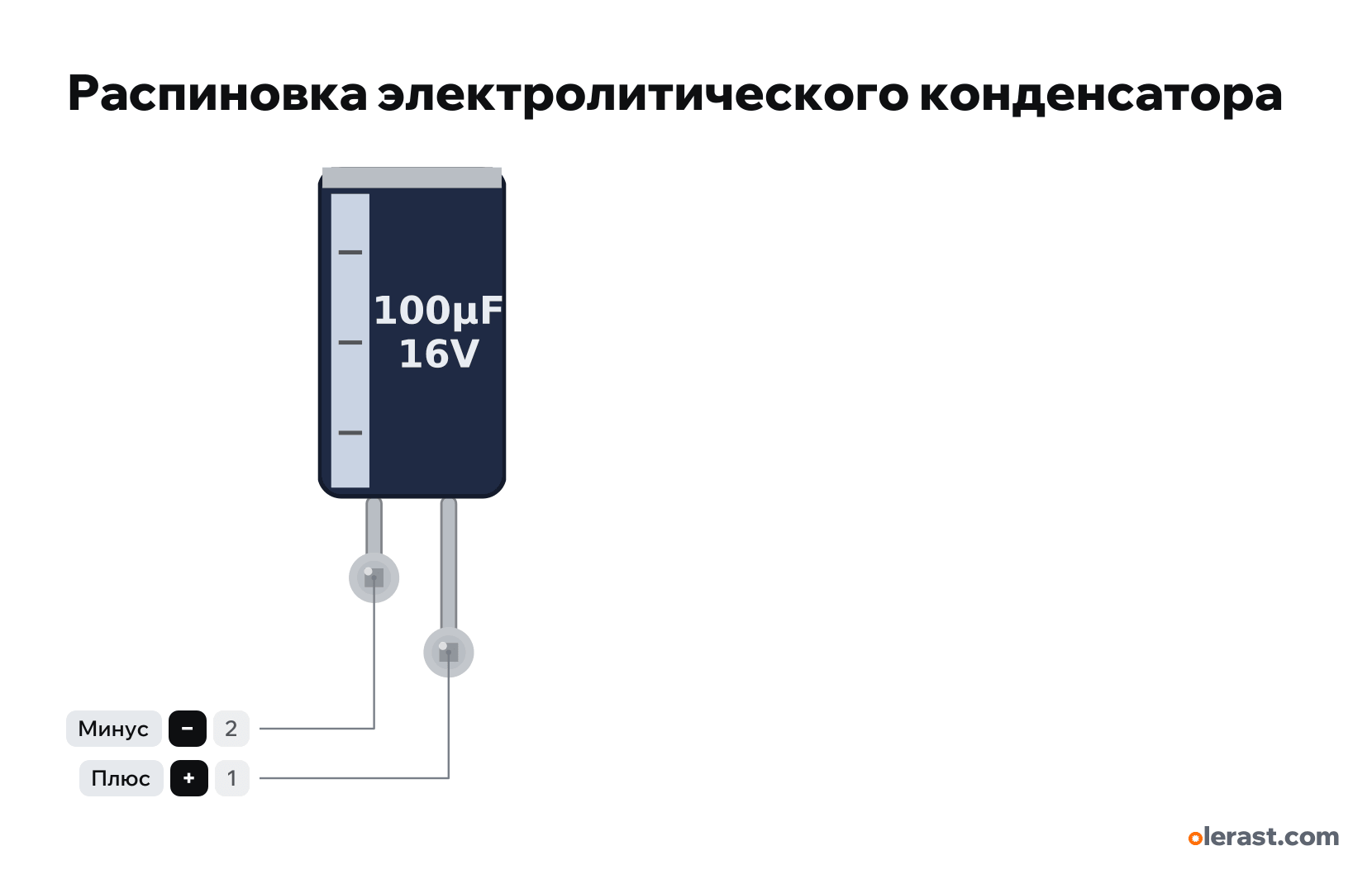
Electrolytic capacitor (polarized, negative marked by a stripe), Electrolytic capacitor, 5 V logic, 6.4×17.4 mm, 2 pins
verified17.10.2026
Front view, negative stripe on the left, leads pointing down: negative on the left (shorter), positive on the right (longer).
Download PNG- Chip
- Electrolytic capacitor
- Logic
- 5 V
Important
- The stripe with "-" signs on the sleeve marks the negative; the long lead is positive.
- Reversed, or above its rated voltage, an electrolytic heats up, bulges and can pop. Pick a voltage rating with margin: for 5 V use 10 V or more, for 12 V use 16 V or more (25 V is better).
- 100-470 µF at the ESP32 and nRF24 supply smooths current peaks during transmission.
All pins
Sources
Every pin is verified against the manufacturer's documents.
- Nichicon UVR series aluminum electrolytic capacitorsdatasheet, checked 17.10.2026radial Ø5-18 mm, Ø6.3×11 for 100 µF 16 V, lead pitch 2.5 mm, negative lead marked on the sleeve
Size: can Ø6.3×11 mm (100 µF 16 V); leads 2.5 mm apart drawn at 2.54 (approximate).