LilyGO T-Display ESP32 pinout
LilyGO T-Display (ESP32, 1,14″ ST7789), ESP32 (ESP32-D0WDQ6), 3.3 V logic, 25.09×51.49 mm, 24 pins
verified17.10.2026
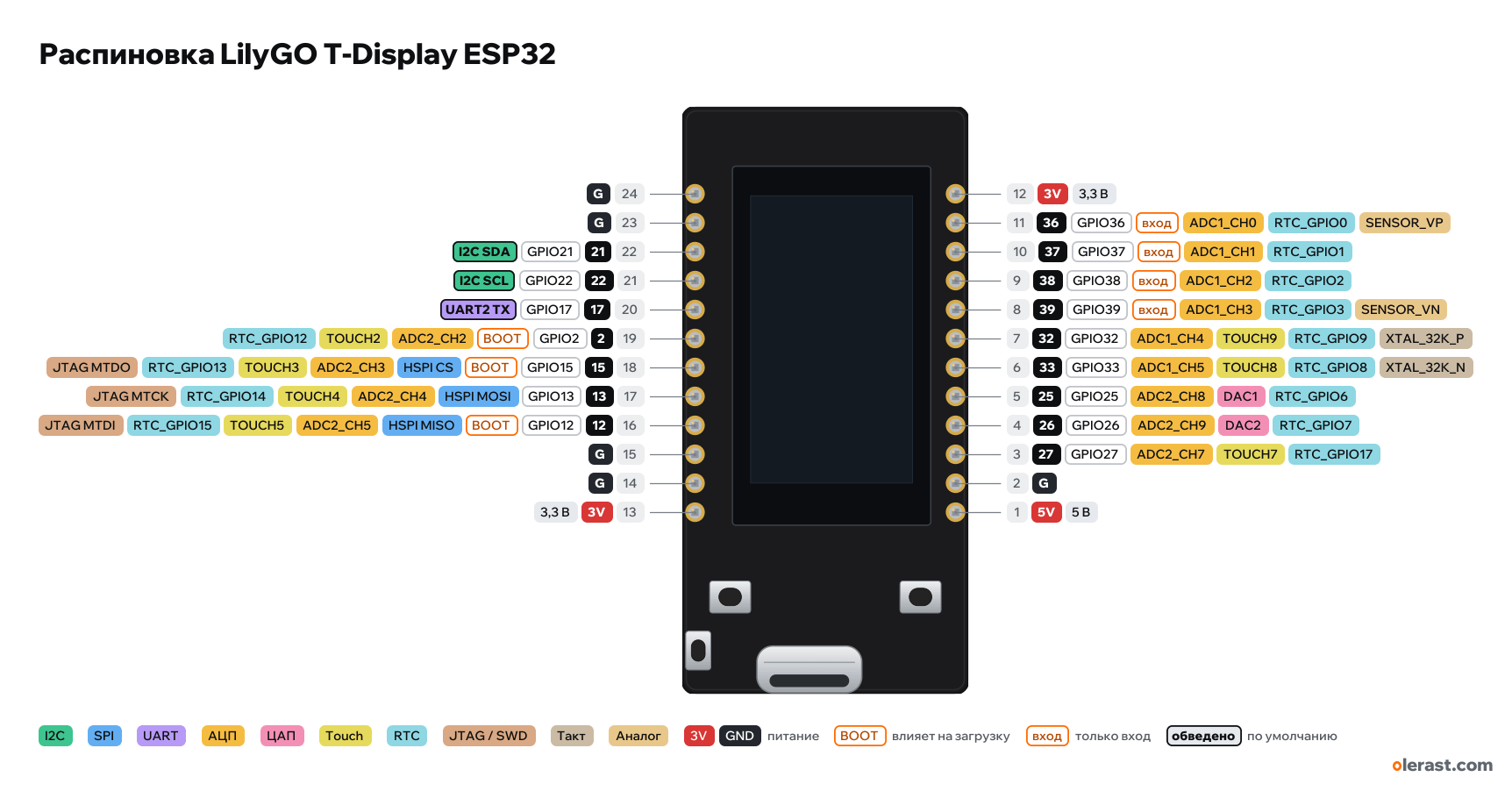
- 24G
- 23G
- 2221GPIO21I2C SDA
- 2122GPIO22I2C SCL
- 2017GPIO17UART2 TX
- 192GPIO2BOOTADC2_CH2TOUCH2RTC_GPIO12
- 1815GPIO15BOOTHSPI CSADC2_CH3TOUCH3RTC_GPIO13JTAG MTDO
- 1713GPIO13HSPI MOSIADC2_CH4TOUCH4RTC_GPIO14JTAG MTCK
- 1612GPIO12BOOTHSPI MISOADC2_CH5TOUCH5RTC_GPIO15JTAG MTDI
- 15G
- 14G
- 133V3.3 V
- 123V3.3 V
- 1136GPIO36inADC1_CH0RTC_GPIO0SENSOR_VP
- 1037GPIO37inADC1_CH1RTC_GPIO1
- 938GPIO38inADC1_CH2RTC_GPIO2
- 839GPIO39inADC1_CH3RTC_GPIO3SENSOR_VN
- 732GPIO32ADC1_CH4TOUCH9RTC_GPIO9XTAL_32K_P
- 633GPIO33ADC1_CH5TOUCH8RTC_GPIO8XTAL_32K_N
- 525GPIO25ADC2_CH8DAC1RTC_GPIO6
- 426GPIO26ADC2_CH9DAC2RTC_GPIO7
- 327GPIO27ADC2_CH7TOUCH7RTC_GPIO17
- 2G
- 15V5 V
View from the display side, USB-C at the bottom.
CompareDownload PNG- Chip
- ESP32 (ESP32-D0WDQ6)
- Logic
- 3.3 V
- Power
- USB-C 4.75-5.25 VLi-ion 3.7 V (JST 1.25 mm connector) 3.3-4.2 V5V 4.75-5.25 V
- Defaults in arduino-esp32 (board "LilyGo T-Display")
- I2C: SDA 21, SCL 22SPI: MOSI 23, MISO 19, SCK 18, SS 5UART: TX 1, RX 3
Which LilyGO T-Display ESP32 pins are safe to use
Free to use
GPIO13, GPIO17, GPIO21, GPIO22, GPIO25-27, GPIO32, GPIO33
Use with care
- GPIO2, GPIO12, GPIO15: strapping: the level at power-up selects the boot mode.
- GPIO36-39: input only, no output and no pull-ups.
Important
- 3.3 V logic, don't put 5 V on the GPIO.
- Pin labels are printed on the back (the front is covered by the display).
- The display uses GPIO4, 5, 16, 18, 19, 23: they are not broken out to the header. Use the TFT_eSPI library with the Setup25_TTGO_T_Display setup.
- Buttons: GPIO0 (BOOT) and GPIO35. Battery voltage: GPIO34 via a divider, the divider is enabled by a high level on GPIO14.
- 36, 37, 38, 39 are inputs only. 37 and 38 exist only on the bare ESP32-D0WDQ6 chip, boards with a WROOM module do not have them.
- Strapping pins on the header: 2, 12, 15. Keep GPIO12 low at power-up.
- Turn off the display backlight (GPIO4) in sleep mode, otherwise the battery drains in hours.
- AP2112K-3.3 regulator (600 mA); the display backlight draws tens of mA, turn it off on battery (GPIO4).
Revisions and clones
- T-Display S3 is a different board (ESP32-S3, 1.9″ display, 8-bit bus), the pins are different.
- Newer boards have a CH9102F instead of the CP2104, the pins are the same.
All pins
| Label | Number | Functions | Limits | Check |
|---|---|---|---|---|
| G | pin 24 | Ground | verified | |
| G | pin 23 | Ground | verified | |
| 21 | GPIO21, pin 22 | interruptPWM (LEDC)I2C SDA | not 5 V tolerant | verified |
| 22 | GPIO22, pin 21 | interruptPWM (LEDC)I2C SCL | not 5 V tolerant | verified |
| 17 | GPIO17, pin 20 | interruptPWM (LEDC)UART2 TX | not 5 V tolerant | verified |
| 2 | GPIO2, pin 19 | interruptPWM (LEDC)ADC2_CH2TOUCH2RTC_GPIO12 | affects boot (strapping)ADC2 doesn't work with Wi-Fi onnot 5 V tolerant | verifiedAt reset it must be low or floating for download mode. Internal pull-down.ADC2: while Wi-Fi is running, analogRead on this pin doesn't work. For ADC with Wi-Fi, use ADC1 (GPIO32–39). |
| 15 | GPIO15, pin 18 | interruptPWM (LEDC)ADC2_CH3TOUCH3RTC_GPIO13HSPI CSJTAG MTDO | affects boot (strapping)ADC2 doesn't work with Wi-Fi onnot 5 V tolerant | verifiedMTDO: low at reset silences the bootloader log on UART0. Internal pull-up.ADC2: while Wi-Fi is running, analogRead on this pin doesn't work. For ADC with Wi-Fi, use ADC1 (GPIO32–39). |
| 13 | GPIO13, pin 17 | interruptPWM (LEDC)ADC2_CH4TOUCH4RTC_GPIO14HSPI MOSIJTAG MTCK | ADC2 doesn't work with Wi-Fi onnot 5 V tolerant | verifiedADC2: while Wi-Fi is running, analogRead on this pin doesn't work. For ADC with Wi-Fi, use ADC1 (GPIO32–39). |
| 12 | GPIO12, pin 16 | interruptPWM (LEDC)ADC2_CH5TOUCH5RTC_GPIO15HSPI MISOJTAG MTDI | affects boot (strapping)ADC2 doesn't work with Wi-Fi onnot 5 V tolerant | verifiedMTDI: selects the flash voltage at reset. High = 1.8 V, so a module with 3.3 V flash won't boot. Internal pull-down.ADC2: while Wi-Fi is running, analogRead on this pin doesn't work. For ADC with Wi-Fi, use ADC1 (GPIO32–39). |
| G | pin 15 | Ground | verified | |
| G | pin 14 | Ground | verified | |
| 3V | pin 13 | 3.3 V | power inputpower output | verified |
| 3V | pin 12 | 3.3 V | power inputpower output | verifiedAP2112K-3.3 regulator output (600 mA, the board with the display takes part of it). |
| 36 | GPIO36, pin 11 | interruptADC1_CH0RTC_GPIO0SENSOR_VP | input onlynot 5 V tolerant | verifiedInput only: no output and no internal pull-ups. |
| 37 | GPIO37, pin 10 | interruptADC1_CH1RTC_GPIO1 | input onlynot 5 V tolerant | verifiedInput only: no output and no internal pull-ups. Broken out only on the bare ESP32-D0WDQ6 chip (QFN-48 6×6); WROOM modules and the D0WD-V3 chip (5×5) do not have it. |
| 38 | GPIO38, pin 9 | interruptADC1_CH2RTC_GPIO2 | input onlynot 5 V tolerant | verifiedInput only: no output and no internal pull-ups. Broken out only on the bare ESP32-D0WDQ6 chip (QFN-48 6×6); WROOM modules and the D0WD-V3 chip (5×5) do not have it. |
| 39 | GPIO39, pin 8 | interruptADC1_CH3RTC_GPIO3SENSOR_VN | input onlynot 5 V tolerant | verifiedInput only: no output and no internal pull-ups. |
| 32 | GPIO32, pin 7 | interruptPWM (LEDC)ADC1_CH4TOUCH9RTC_GPIO9XTAL_32K_P (32 kHz crystal) | not 5 V tolerant | verified |
| 33 | GPIO33, pin 6 | interruptPWM (LEDC)ADC1_CH5TOUCH8RTC_GPIO8XTAL_32K_N (32 kHz crystal) | not 5 V tolerant | verified |
| 25 | GPIO25, pin 5 | interruptPWM (LEDC)ADC2_CH8RTC_GPIO6DAC1 | ADC2 doesn't work with Wi-Fi onnot 5 V tolerant | verifiedADC2: while Wi-Fi is running, analogRead on this pin doesn't work. For ADC with Wi-Fi, use ADC1 (GPIO32–39). |
| 26 | GPIO26, pin 4 | interruptPWM (LEDC)ADC2_CH9RTC_GPIO7DAC2 | ADC2 doesn't work with Wi-Fi onnot 5 V tolerant | verifiedADC2: while Wi-Fi is running, analogRead on this pin doesn't work. For ADC with Wi-Fi, use ADC1 (GPIO32–39). |
| 27 | GPIO27, pin 3 | interruptPWM (LEDC)ADC2_CH7TOUCH7RTC_GPIO17 | ADC2 doesn't work with Wi-Fi onnot 5 V tolerant | verifiedADC2: while Wi-Fi is running, analogRead on this pin doesn't work. For ADC with Wi-Fi, use ADC1 (GPIO32–39). |
| G | pin 2 | Ground | verified | |
| 5V | pin 1 | 5 V | power inputpower output | verified5 V from USB-C or a 5 V input. |
Sources
Every pin is verified against the manufacturer's documents.
- LilyGO TTGO-T-Display: README, Pinout tableuser guide, checked 17.10.2026display: MOSI 19, SCLK 18, CS 5, DC 16, RST 23, BL 4; buttons 35 and 0; ADC_IN (battery) 34, divider power 14; I2C 21/22
- LilyGO TTGO-T-Display: kicad/TTGO_T_Display (symbol and footprint)board drawing, checked 17.10.202624 pins with numbers and nets, pad coordinates, rows 22.86 mm apart, outline 25.09×51.49 mm, USB position
- LilyGO ESP32-TFT(6-26) schematicschematic, checked 17.10.2026ESP32-D0WDQ6, CP2104, AP2112K-3.3, TP4054, ST7789, BAT_ADC battery divider
- arduino-esp32: variants/lilygo_t_display/pins_arduino.hArduino core, checked 17.10.2026TX 1, RX 3, SDA 21, SCL 22, SS 5, MOSI 23, MISO 19, SCK 18, VBAT 34, buttons 35 and 0, USB PID 0x55D4 (CH9102)
- ESP32 Series Datasheet (Espressif)datasheet, checked 15.10.2026IO MUX and pin functions, ADC1/ADC2, touch, DAC, RTC GPIO, strapping (GPIO0, 2, 5, 12, 15), flash pins GPIO6–11, input-only GPIO34–39
- ESP-IDF: GPIO & RTC GPIO (ESP32)user guide, checked 15.10.2026GPIO6–11 used by flash, GPIO34–39 input only with no pull-ups, strapping pins, GPIO1/3 UART0
- ESP-IDF: ADC Oneshot Mode Driver (ESP32)user guide, checked 15.10.2026ADC2 can't be used while Wi-Fi is running
- arduino-esp32: variants/esp32/pins_arduino.hArduino core, checked 15.10.2026defaults: TX 1, RX 3, SDA 21, SCL 22, SS 5, MOSI 23, MISO 19, SCK 18
Size: from the LilyGO KiCad footprint (silkscreen outline).
FAQ
- Which LilyGO T-Display ESP32 pins are I2C, SPI and UART?
- By default in arduino-esp32 (board "LilyGo T-Display"): I2C: SDA GPIO21, SCL GPIO22; SPI: MOSI GPIO23, MISO GPIO19, SCK GPIO18, SS GPIO5; UART: TX GPIO1, RX GPIO3.
- Are the LilyGO T-Display ESP32 pins 5 V tolerant?
- No. The logic is 3.3 V and the pins are not 5 V tolerant: use a divider or a level shifter for 5 V signals.
- Does ADC2 on the LilyGO T-Display ESP32 work with Wi-Fi on?
- No. ADC2 pins (GPIO2, GPIO12, GPIO13, GPIO15, GPIO25-27) can't read analog while Wi-Fi is on. With Wi-Fi, use GPIO32, GPIO33, GPIO36-39 for the ADC.
You might also need
Schematic with this board
schematic builder with the board already placed
Flash this board
upload a sketch or .bin to this board from the browser
Power budget
will the regulator cope and how long the battery lasts
Calculators
LED resistor, voltage divider, battery runtime, 3D print cost, LED strip power supply and pF, nF, µF conversion
Similar boards
Next
- Emotion keychainmy ESP32 project, prototype
- ESP32 music playermy ESP32 project, prototype
- DITHR//CAMmy ESP32 project, prototype
Need firmware or a device built on ESP32? I'll build it to order