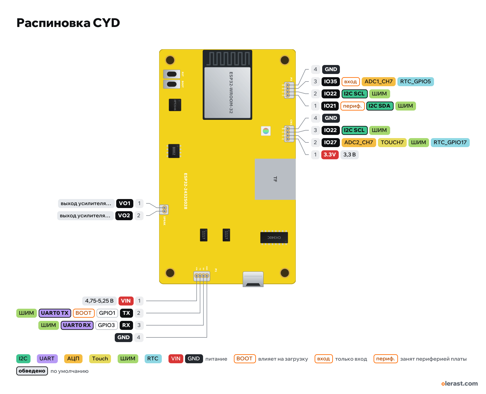
CYD pinout
CYD, Cheap Yellow Display (Sunton ESP32-2432S028R, 2,8″), ESP32 (ESP32-D0WD), 3.3 V logic, 86×50 mm, 14 pins
Component side view (back of the display), ESP32 on the left, micro-USB on the right; the display is on the other side, rotated 90° on the diagram.
BuyCompareDownload PNG- Chip
- ESP32 (ESP32-D0WD), ESP32-WROOM-32 (4 MB flash)
- Logic
- 3.3 V
- Power
- Micro-USB 4.75-5.25 VVIN (P1 connector) 4.75-5.25 V
- Defaults in arduino-esp32 (ESP32 Dev Module), TFT_eSPI display
- UART: TX 1, RX 3
Which CYD pins are safe to use
Free to use
GPIO3, GPIO22
Use with care
- GPIO1: signal at boot.
- GPIO21: onboard peripherals are wired to them.
- GPIO27: onboard pull-up or divider.
- GPIO35: input only, no output and no pull-ups.
Important
- 3.3 V logic, don't put 5 V on the GPIO.
- Free on the connectors: GPIO22 (P3 and CN1), GPIO27 (CN1, 10 kΩ pull-up on the board), GPIO35 (P3, input only). GPIO21 on P3 controls the display backlight.
- Arduino's default I2C is on GPIO21/22. GPIO21 is used by the backlight, so connect I2C sensors to CN1: Wire.begin(27, 22).
- ILI9341 display on HSPI: SCK 14, MOSI 13, MISO 12, CS 15, DC 2, backlight 21. The display reset is tied to the board's EN.
- XPT2046 touch: CLK 25, MOSI 32, MISO 39, CS 33, IRQ 36. microSD card: SS 5, SCK 18, MISO 19, MOSI 23 (VSPI).
- The touch controller and the card are on different pins and share no bus: connect the touch controller with a separate SPIClass using its own pins, or with software SPI.
- RGB LED on the back: red GPIO4, green GPIO16, blue GPIO17, lit when LOW. If you do not need the LED, you can reclaim these three GPIOs by desoldering it.
- Photoresistor on the front side next to the display: GPIO34 via a 1 MΩ divider.
- Speaker on P4: SC8002B amplifier, input from GPIO26 (DAC2).
- TX and RX on P1 are connected to the CH340C: Serial is busy while USB is connected.
- Used internally: GPIO2, 4, 5, 12-19, 21, 23, 25, 26, 32-34, 36, 39. GPIO0 is on the BOOT button.
- Board connectors are Molex PicoBlade 1.25 mm (sold as "MX1.25"); the schematic lists P4 as PH 2.0.
- Connector and component positions were measured from the Sunton drawing (±0.5 mm).
- Two AMS1117-3.3 regulators: one powers the ESP32, the other powers the display, touch controller, card, CH340C, amplifier and the 3.3V pin on CN1.
- Sunton spec: current about 115 mA.
Revisions and clones
- Version with two USB ports (micro-USB and USB-C, "CYD2USB"): ST7789 display, colors inverted, needs its own TFT_eSPI setup. USB-C has no CC resistors: it does not work with a USB-C to USB-C cable, use a cable from USB-A.
- Sunton V0.1 schematic (2022): CN1 pin 3 is unconnected, labeled "NC". On boards from reviews it is GPIO22.
- ESP32-2432S024, ESP32-3248S035 and similar yellow boards with a display: different pins, these are different boards.
All pins
| Label | Number | Functions | Limits | Check |
|---|---|---|---|---|
| IO21 | GPIO21, pin 1 | interruptPWM (LEDC)I2C SDA | not 5 V tolerantused by onboard peripherals (camera, card, display) | verifiedDisplay backlight via an AO3402 transistor: HIGH = backlight on. Also routed to P3 in parallel, not suitable for your own sensors. |
| IO22 | GPIO22, pin 2 | interruptPWM (LEDC)I2C SCL | not 5 V tolerant | verifiedFree. The same GPIO22 is also routed to CN1. |
| IO35 | GPIO35, pin 3 | interruptADC1_CH7RTC_GPIO5 | input onlynot 5 V tolerant | verifiedInput only: no output and no internal pull-ups.Free, input only, no internal pull-ups. |
| GND | pin 4 | Ground | verified | |
| 3.3V | pin 1 | 3.3 V | power output | verified3.3 V from the second AMS1117 (the one that powers the display, card and touch controller).Labelled on other revisions as: 3V3 |
| IO27 | GPIO27, pin 2 | interruptPWM (LEDC)ADC2_CH7TOUCH7RTC_GPIO17 | ADC2 doesn't work with Wi-Fi onnot 5 V tolerantonboard pull-up | verifiedADC2: while Wi-Fi is running, analogRead on this pin doesn't work. For ADC with Wi-Fi, use ADC1 (GPIO32–39).Free. The board has a 10 kΩ pull-up to 3.3 V (R18). |
| IO22 | GPIO22, pin 3 | interruptPWM (LEDC)I2C SCL | not 5 V tolerant | not from manufacturerOn the Sunton V0.1 (2022) schematic, CN1 pin 3 has no net, and the manufacturer's drawing labels it "NC". witnessmenow (PINS.md) and Random Nerd Tutorials say GPIO22. Check with a continuity tester on your board.GPIO22, in parallel with pin P3-2.Labelled on other revisions as: NC |
| GND | pin 4 | Ground | verified | |
| VIN | pin 1 | 5 V | power inputpower output | verified5 V input via AO3401 to the 5 V rail. When powered from USB it carries about 5 V (after the 1N5819 diode). |
| TX | GPIO1, pin 2 | interruptPWM (LEDC)UART0 TX | outputs a signal at bootnot 5 V tolerant | verifiedPrints the bootloader log at boot (115200 baud).UART0 TX via 100 Ω. Also connected to the CH340C: busy during flashing and Serial. |
| RX | GPIO3, pin 3 | interruptPWM (LEDC)UART0 RX | not 5 V tolerant | verifiedUART0 RX via 100 Ω. Also connected to the CH340C: busy during flashing and Serial. |
| GND | pin 4 | Ground | verified | |
| VO1 | pin 1 | SC8002B amplifier output (VO1) | not from manufacturerThe manufacturer's drawing does not show which P4 pin is first. For a speaker the order does not matter.Bridge amplifier output of the SC8002B, amplifier input from GPIO26 (DAC2). Do not connect either pin to GND. | |
| VO2 | pin 2 | SC8002B amplifier output (VO2) | not from manufacturerThe manufacturer's drawing does not show which P4 pin is first. For a speaker the order does not matter. |
Sources
Not verified against the manufacturer: 3 of 14 pins. The pin card says what confirms each one and where sources disagree.
- Sunton: ESP32-2432S028R Specifications (EN), copy in the witnessmenow repositorydatasheet, checked 20.10.2026size 50×86 mm, ILI9341 320×240, active area 43.2×57.6 mm, 5 V supply, current about 115 mA, layout drawing of P3, CN1, TF, P1, P4, RESET and BOOT buttons, connector labels (P3: GND IO35 IO22 IO21, CN1: GND NC IO27 3.3V, P1: VIN TX RX GND)
- Sunton: ESP32-2432S028 V0.1 schematic (2022), MCU and LCM sheetsschematic, checked 20.10.2026P1: 1 VIN, 2 TX (U0TXD via 100 Ω), 3 RX (U0RXD via 100 Ω), 4 GND; P3: 1 IO21, 2 IO22, 3 IO35, 4 GND; CN1: 1 3.3V, 2 IO27 (10 kΩ to 3.3 V), 3 no net, 4 GND; P4: SC8002B outputs; display, XPT2046, SD, RGB, photoresistor GPIO34, backlight GPIO21 via AO3402, two AMS1117-3.3, CH340C, AO3401 on VIN, 1N5819 on USB
- Sunton: board dimension drawing (Dimensions.png)board drawing, checked 20.10.202650×86 mm, holes 4 mm from the edges, corner radius R1.6
- witnessmenow/ESP32-Cheap-Yellow-Display: PINS.mdthird-party source, checked 20.10.2026Molex PicoBlade 1.25 mm connectors; CN1: GND, IO22, IO27, 3.3V; free GPIOs 35, 22, 27; RGB 4/16/17 lit when LOW; SD on VSPI 5/18/19/23; touch 25/32/33/36/39; display HSPI 2/12/13/14/15, backlight 21; speaker GPIO26 via amplifier
- witnessmenow: cyd.md and DisplayConfig/CYD2USB/User_Setup.hthird-party source, checked 20.10.2026version with micro-USB and USB-C: display on ST7789 with inverted colors, no CC resistors on USB-C
- Random Nerd Tutorials: ESP32 Cheap Yellow Display (CYD) Pinoutthird-party source, checked 20.10.2026photoresistor on the front side next to the display (GPIO34), CN1: GND, GPIO22, GPIO27, 3V3, RGB LED on the back
- ESP32 Series Datasheet (Espressif)datasheet, checked 15.10.2026IO MUX and pin functions, ADC1/ADC2, touch, DAC, RTC GPIO, strapping (GPIO0, 2, 5, 12, 15), flash pins GPIO6–11, input-only GPIO34–39
- ESP-IDF: GPIO & RTC GPIO (ESP32)user guide, checked 15.10.2026GPIO6–11 used by flash, GPIO34–39 input only with no pull-ups, strapping pins, GPIO1/3 UART0
- ESP-IDF: ADC Oneshot Mode Driver (ESP32)user guide, checked 15.10.2026ADC2 can't be used while Wi-Fi is running
- arduino-esp32: variants/esp32/pins_arduino.hArduino core, checked 15.10.2026defaults: TX 1, RX 3, SDA 21, SCL 22, SS 5, MOSI 23, MISO 19, SCK 18
Size: 50×86 mm per the Sunton spec and dimension drawing; holes 4 mm from the edges.
FAQ
- Which CYD pins are I2C, SPI and UART?
- By default in arduino-esp32 (ESP32 Dev Module), TFT_eSPI display: UART: TX GPIO1, RX GPIO3.
- Are the CYD pins 5 V tolerant?
- No. The logic is 3.3 V and the pins are not 5 V tolerant: use a divider or a level shifter for 5 V signals.
- Does ADC2 on the CYD work with Wi-Fi on?
- No. ADC2 pins (GPIO27) can't read analog while Wi-Fi is on. With Wi-Fi, use GPIO35 for the ADC.
You might also need
Schematic with this board
schematic builder with the board already placed
Flash this board
upload a sketch or .bin to this board from the browser
Power budget
will the regulator cope and how long the battery lasts
Calculators
LED resistor, voltage divider, battery runtime, 3D print cost, LED strip power supply and pF, nF, µF conversion
Similar boards

Next
- Emotion keychainmy ESP32 project, prototype
- ESP32 music playermy ESP32 project, prototype
- DITHR//CAMmy ESP32 project, prototype
Need firmware or a device built on ESP32? I'll build it to order