ESP32-CAM pinout
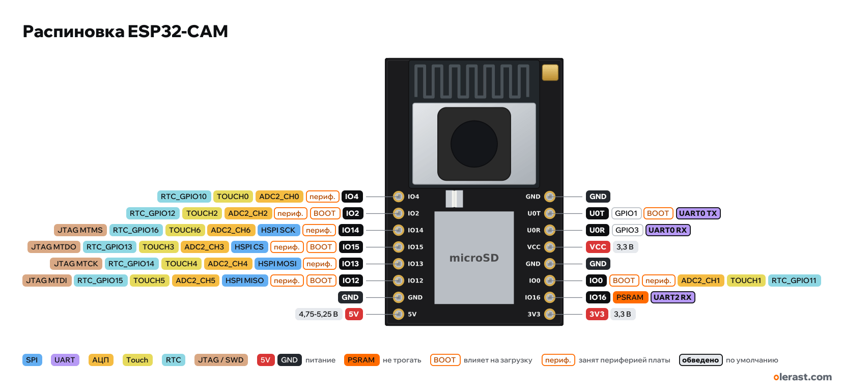
ESP32-CAM (AI-Thinker), ESP32 (ESP32-D0WDQ6), 3.3 V logic, 27×40.5 mm, 16 pins
partly verified17.10.2026
- IO4periph.ADC2_CH0TOUCH0RTC_GPIO10
- IO2BOOTperiph.ADC2_CH2TOUCH2RTC_GPIO12
- IO14periph.HSPI SCKADC2_CH6TOUCH6RTC_GPIO16JTAG MTMS
- IO15BOOTperiph.HSPI CSADC2_CH3TOUCH3RTC_GPIO13JTAG MTDO
- IO13periph.HSPI MOSIADC2_CH4TOUCH4RTC_GPIO14JTAG MTCK
- IO12BOOTperiph.HSPI MISOADC2_CH5TOUCH5RTC_GPIO15JTAG MTDI
- GND
- 5V4.75-5.25 V
View from the camera side, antenna at the top.
BuyCompareDownload PNG- Chip
- ESP32 (ESP32-D0WDQ6), ESP32-S (AI-Thinker) + PSRAM 4–8 MB
- Logic
- 3.3 V
- Power
- 5V 4.75-5.25 V3V3 3-3.6 V
- Defaults in arduino-esp32 ("AI Thinker ESP32-CAM" board)
- UART: TX 1, RX 3LED: 33
Which ESP32-CAM pins are safe to use
Free to use
GPIO3
Use with care
- GPIO0, GPIO2, GPIO12, GPIO15: strapping: the level at power-up selects the boot mode.
- GPIO1: signal at boot.
- GPIO4, GPIO13, GPIO14: onboard peripherals are wired to them.
Leave alone
- GPIO16: flash and PSRAM memory.
Important
- 3.3 V logic, don't put 5 V on the GPIO.
- The camera uses GPIO0, 5, 18, 19, 21-23, 25-27, 32, 34-36, 39: of these only GPIO0 (XCLK) is brought out to the header.
- A microSD card in 4-bit mode uses GPIO2, 4, 12, 13, 14, 15, which is almost all the free header pins. In 1-bit mode (SD_MMC.begin("/sdcard", true)) 4, 12, 13 are free.
- GPIO16 is used by PSRAM, GPIO1 and 3 are UART0 for flashing. Without the card, 2, 4, 12, 13, 14, 15 remain for your own sensors.
- Flashing: IO0 to GND, reset (RST button on the back), upload, remove the jumper, reset.
- Strapping pins on the header: IO0, IO2, IO12, IO15. Keep GPIO12 low at power-up.
- Red LED on GPIO33 (on when LOW) on the back, not brought out to the header.
- The board draws up to 300 mA with Wi-Fi and the camera and more with the flash: power it with 5 V from a 1-2 A source, not from the 3.3 V pin of an adapter.
- No USB on the board: flash through a USB-UART adapter (U0R, U0T, GND, 5V) or the ESP32-CAM-MB board.
- AI-Thinker: with weak power the image has stripes and the board resets when the camera starts.
Revisions and clones
- Clones (ESP32-CAM "HW-297" and similar) copy the AI-Thinker board; some have 4 MB PSRAM and no VCC jumper.
- ESP32-CAM-MB is a base board with a CH340 and micro-USB: the ESP32-CAM plugs on top and is flashed over USB.
All pins
| Label | Number | Functions | Limits | Check |
|---|---|---|---|---|
| 5V | 5 V | power input | not from manufacturerThe order of the 16 pins follows common pinouts and the AI-Thinker drawing; the ESP32_CAM_V1.6 schematic from the AI-Thinker site could not be downloaded, so it was not checked against it.5 V input to the AMS1117-3.3 regulator. | |
| GND | Ground | not from manufacturerThe order of the 16 pins follows common pinouts and the AI-Thinker drawing; the ESP32_CAM_V1.6 schematic from the AI-Thinker site could not be downloaded, so it was not checked against it. | ||
| IO12 | GPIO12 | interruptPWM (LEDC)ADC2_CH5TOUCH5RTC_GPIO15HSPI MISOJTAG MTDI | affects boot (strapping)ADC2 doesn't work with Wi-Fi onnot 5 V tolerantused by onboard peripherals (camera, card, display) | not from manufacturerThe order of the 16 pins follows common pinouts and the AI-Thinker drawing; the ESP32_CAM_V1.6 schematic from the AI-Thinker site could not be downloaded, so it was not checked against it.MTDI: selects the flash voltage at reset. High = 1.8 V, so a module with 3.3 V flash won't boot. Internal pull-down.ADC2: while Wi-Fi is running, analogRead on this pin doesn't work. For ADC with Wi-Fi, use ADC1 (GPIO32–39).microSD card line (DATA2). Free if the card is not used or runs in 1-bit mode (which needs only GPIO2, 14, 15). |
| IO13 | GPIO13 | interruptPWM (LEDC)ADC2_CH4TOUCH4RTC_GPIO14HSPI MOSIJTAG MTCK | ADC2 doesn't work with Wi-Fi onnot 5 V tolerantused by onboard peripherals (camera, card, display) | not from manufacturerThe order of the 16 pins follows common pinouts and the AI-Thinker drawing; the ESP32_CAM_V1.6 schematic from the AI-Thinker site could not be downloaded, so it was not checked against it.ADC2: while Wi-Fi is running, analogRead on this pin doesn't work. For ADC with Wi-Fi, use ADC1 (GPIO32–39).microSD card line (DATA3). Free if the card is not used or runs in 1-bit mode (which needs only GPIO2, 14, 15). |
| IO15 | GPIO15 | interruptPWM (LEDC)ADC2_CH3TOUCH3RTC_GPIO13HSPI CSJTAG MTDO | affects boot (strapping)ADC2 doesn't work with Wi-Fi onnot 5 V tolerantused by onboard peripherals (camera, card, display) | not from manufacturerThe order of the 16 pins follows common pinouts and the AI-Thinker drawing; the ESP32_CAM_V1.6 schematic from the AI-Thinker site could not be downloaded, so it was not checked against it.MTDO: low at reset silences the bootloader log on UART0. Internal pull-up.ADC2: while Wi-Fi is running, analogRead on this pin doesn't work. For ADC with Wi-Fi, use ADC1 (GPIO32–39).microSD card line (CMD). Free if the card is not used or runs in 1-bit mode (which needs only GPIO2, 14, 15). |
| IO14 | GPIO14 | interruptPWM (LEDC)ADC2_CH6TOUCH6RTC_GPIO16HSPI SCKJTAG MTMS | ADC2 doesn't work with Wi-Fi onnot 5 V tolerantused by onboard peripherals (camera, card, display) | not from manufacturerThe order of the 16 pins follows common pinouts and the AI-Thinker drawing; the ESP32_CAM_V1.6 schematic from the AI-Thinker site could not be downloaded, so it was not checked against it.ADC2: while Wi-Fi is running, analogRead on this pin doesn't work. For ADC with Wi-Fi, use ADC1 (GPIO32–39).microSD card line (CLK). Free if the card is not used or runs in 1-bit mode (which needs only GPIO2, 14, 15). |
| IO2 | GPIO2 | interruptPWM (LEDC)ADC2_CH2TOUCH2RTC_GPIO12 | affects boot (strapping)ADC2 doesn't work with Wi-Fi onnot 5 V tolerantused by onboard peripherals (camera, card, display) | not from manufacturerThe order of the 16 pins follows common pinouts and the AI-Thinker drawing; the ESP32_CAM_V1.6 schematic from the AI-Thinker site could not be downloaded, so it was not checked against it.At reset it must be low or floating for download mode. Internal pull-down.ADC2: while Wi-Fi is running, analogRead on this pin doesn't work. For ADC with Wi-Fi, use ADC1 (GPIO32–39).microSD card line (DATA0). Free if the card is not used or runs in 1-bit mode (which needs only GPIO2, 14, 15). |
| IO4 | GPIO4 | interruptPWM (LEDC)ADC2_CH0TOUCH0RTC_GPIO10 | ADC2 doesn't work with Wi-Fi onnot 5 V tolerantused by onboard peripherals (camera, card, display) | not from manufacturerThe order of the 16 pins follows common pinouts and the AI-Thinker drawing; the ESP32_CAM_V1.6 schematic from the AI-Thinker site could not be downloaded, so it was not checked against it.ADC2: while Wi-Fi is running, analogRead on this pin doesn't work. For ADC with Wi-Fi, use ADC1 (GPIO32–39).microSD card line (DATA1). Free if the card is not used or runs in 1-bit mode (which needs only GPIO2, 14, 15).It also drives the bright white flash LED through a transistor: HIGH = flash on. With the card in 4-bit mode the flash flickers. |
| 3V3 | 3.3 V | power inputpower output | not from manufacturerThe order of the 16 pins follows common pinouts and the AI-Thinker drawing; the ESP32_CAM_V1.6 schematic from the AI-Thinker site could not be downloaded, so it was not checked against it.AMS1117-3.3 regulator output or 3.3 V input. | |
| IO16 | GPIO16 | interruptPWM (LEDC)UART2 RX | not 5 V tolerantused by PSRAM, do not use | not from manufacturerThe order of the 16 pins follows common pinouts and the AI-Thinker drawing; the ESP32_CAM_V1.6 schematic from the AI-Thinker site could not be downloaded, so it was not checked against it.On the ESP32-S module with PSRAM this is the PSRAM CS: do not use. |
| IO0 | GPIO0 | interruptPWM (LEDC)ADC2_CH1TOUCH1RTC_GPIO11 | affects boot (strapping)ADC2 doesn't work with Wi-Fi onnot 5 V tolerantused by onboard peripherals (camera, card, display) | not from manufacturerThe order of the 16 pins follows common pinouts and the AI-Thinker drawing; the ESP32_CAM_V1.6 schematic from the AI-Thinker site could not be downloaded, so it was not checked against it.At reset: low = firmware download mode (BOOT button). Internal pull-up.ADC2: while Wi-Fi is running, analogRead on this pin doesn't work. For ADC with Wi-Fi, use ADC1 (GPIO32–39).Used by the OV2640 camera (XCLK, the camera clock). Tie to GND at power-up to enter bootloader mode. |
| GND | Ground | not from manufacturerThe order of the 16 pins follows common pinouts and the AI-Thinker drawing; the ESP32_CAM_V1.6 schematic from the AI-Thinker site could not be downloaded, so it was not checked against it. | ||
| VCC | 3.3 V | power output | not from manufacturerThe order of the 16 pins follows common pinouts and the AI-Thinker drawing; the ESP32_CAM_V1.6 schematic from the AI-Thinker site could not be downloaded, so it was not checked against it.Power output for modules: 3.3 V by default, switched to 5 V with a 0 Ω jumper on the board. | |
| U0R | GPIO3 | interruptPWM (LEDC)UART0 RX | not 5 V tolerant | not from manufacturerThe order of the 16 pins follows common pinouts and the AI-Thinker drawing; the ESP32_CAM_V1.6 schematic from the AI-Thinker site could not be downloaded, so it was not checked against it.UART0 RX: connect the adapter TX here for flashing and Serial. |
| U0T | GPIO1 | interruptPWM (LEDC)UART0 TX | outputs a signal at bootnot 5 V tolerant | not from manufacturerThe order of the 16 pins follows common pinouts and the AI-Thinker drawing; the ESP32_CAM_V1.6 schematic from the AI-Thinker site could not be downloaded, so it was not checked against it.Prints the bootloader log at boot (115200 baud).UART0 TX: connect the adapter RX here for flashing and Serial. |
| GND | Ground | not from manufacturerThe order of the 16 pins follows common pinouts and the AI-Thinker drawing; the ESP32_CAM_V1.6 schematic from the AI-Thinker site could not be downloaded, so it was not checked against it. |
Sources
Not verified against the manufacturer: 16 of 16 pins. The pin card says what confirms each one and where sources disagree.
- Espressif arduino-esp32: CameraWebServer/camera_pins.h, CAMERA_MODEL_AI_THINKERArduino core, checked 17.10.2026camera: PWDN 32, XCLK 0, SIOD 26, SIOC 27, Y2-Y9 = 5, 18, 19, 21, 36, 39, 34, 35, VSYNC 25, HREF 23, PCLK 22; flash GPIO4, plain LED GPIO33
- AI-Thinker: ESP32-CAM (documentation, Pin definition section, drawing)user guide, checked 17.10.202616 pins, powered from 5 V 2 A, GPIO32 controls camera power, 8 MB PSRAM (4 MB in older descriptions)
- Zephyr: Ai-Thinker ESP32-CAMthird-party source, checked 17.10.20268 MB PSRAM, FPC-24 camera connector, microSD slot, flash
- ESP32 Series Datasheet (Espressif)datasheet, checked 15.10.2026IO MUX and pin functions, ADC1/ADC2, touch, DAC, RTC GPIO, strapping (GPIO0, 2, 5, 12, 15), flash pins GPIO6–11, input-only GPIO34–39
- ESP-IDF: GPIO & RTC GPIO (ESP32)user guide, checked 15.10.2026GPIO6–11 used by flash, GPIO34–39 input only with no pull-ups, strapping pins, GPIO1/3 UART0
- ESP-IDF: ADC Oneshot Mode Driver (ESP32)user guide, checked 15.10.2026ADC2 can't be used while Wi-Fi is running
- arduino-esp32: variants/esp32/pins_arduino.hArduino core, checked 15.10.2026defaults: TX 1, RX 3, SDA 21, SCL 22, SS 5, MOSI 23, MISO 19, SCK 18
Size: 27×40.5 mm per the AI-Thinker description; rows 0.9 inch apart, position from the photo.
FAQ
- Which ESP32-CAM pins are I2C, SPI and UART?
- By default in arduino-esp32 ("AI Thinker ESP32-CAM" board): UART: TX GPIO1, RX GPIO3.
- Which pin is the ESP32-CAM LED on?
- White flash LED on GPIO4 (through a transistor, HIGH = on).
- Are the ESP32-CAM pins 5 V tolerant?
- No. The logic is 3.3 V and the pins are not 5 V tolerant: use a divider or a level shifter for 5 V signals.
- Does ADC2 on the ESP32-CAM work with Wi-Fi on?
- No. ADC2 pins (GPIO0, GPIO2, GPIO4, GPIO12-15) can't read analog while Wi-Fi is on.
You might also need
Similar boards
Next
- Emotion keychainmy ESP32 project, prototype
- ESP32 music playermy ESP32 project, prototype
- DITHR//CAMmy ESP32 project, prototype
Need firmware or a device built on ESP32? I'll build it to order