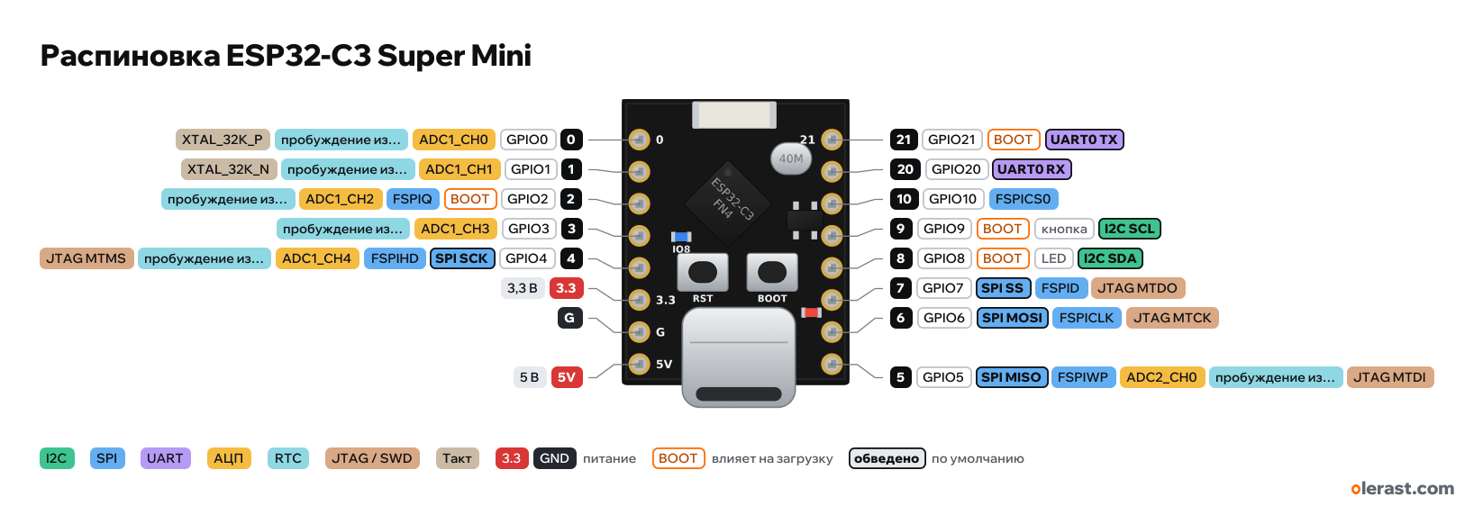
ESP32-C3 Super Mini pinout
ESP32-C3 SuperMini, ESP32-C3, 3.3 V logic, 18×22.52 mm, 16 pins
verified15.10.2026
Top view, USB-C at the bottom, ceramic antenna at the top (in the manufacturer's drawing the board is rotated with USB at the top).
BuyCompareDownload PNG- Chip
- ESP32-C3
- Logic
- 3.3 V
- Power
- USB-C 4.75-5.25 V5V 4.5-5.5 V3.3 3-3.6 V
- Defaults in arduino-esp32 (Nologo ESP32C3 Super Mini)
- I2C: SDA 8, SCL 9SPI: MOSI 6, MISO 5, SCK 4, SS 7UART: TX 21, RX 20LED: 8
Which ESP32-C3 Super Mini pins are safe to use
Free to use
GPIO0, GPIO1, GPIO3-7, GPIO10, GPIO20
Use with care
- GPIO2, GPIO8, GPIO9: strapping: the level at power-up selects the boot mode.
- GPIO21: signal at boot.
Important
- 3.3 V logic, don't put 5 V on the GPIO.
- USB-C goes straight to the chip (GPIO18/19), there is no USB-UART bridge. If the sketch hangs or has taken over USB, flash with BOOT held.
- In Arduino enable "USB CDC On Boot", otherwise Serial is not visible in the serial monitor.
- Strapping: GPIO2, 8, 9. Do not pull GPIO8 and GPIO9 to ground at power-up (except BOOT for flashing).
- GPIO8 LED = SDA, GPIO9 button = SCL by default in Arduino: with I2C on these pins the LED blinks.
- ADC: GPIO0–4 (ADC1). GPIO5 is ADC2, which works poorly according to the errata.
- The silkscreen on top labels only 5V, G, 3.3, 0 and 21; the other numbers are on the back.
- The position of the first pin and of small components was measured from the manufacturer's render (±0.3 mm).
Revisions and clones
- Early boards: the antenna is close to ground and poorly matched, Wi-Fi is weak. In newer revisions the antenna was moved away (per one source).
- Boards with an IPEX connector and a different antenna exist.
- SuperMini Plus: red solder mask, RGB WS2812 on GPIO8, U.FL connector, same pinout.
All pins
| Label | Number | Functions | Limits | Check |
|---|---|---|---|---|
| 0 | GPIO0 | interruptPWM (LEDC)ADC1_CH0wake from deep sleep (deep sleep GPIO)XTAL_32K_P | not 5 V tolerant | verified |
| 1 | GPIO1 | interruptPWM (LEDC)ADC1_CH1wake from deep sleep (deep sleep GPIO)XTAL_32K_N | not 5 V tolerant | verified |
| 2 | GPIO2 | interruptPWM (LEDC)ADC1_CH2wake from deep sleep (deep sleep GPIO)FSPIQ | not 5 V tolerantaffects boot (strapping)onboard pull-up | verifiedStrapping: floating by default, Espressif recommends a pull-up. Do not pull low at reset.10 kΩ pull-up to 3.3 V on the board. |
| 3 | GPIO3 | interruptPWM (LEDC)ADC1_CH3wake from deep sleep (deep sleep GPIO) | not 5 V tolerant | verified |
| 4 | GPIO4 | interruptPWM (LEDC)ADC1_CH4wake from deep sleep (deep sleep GPIO)JTAG MTMSFSPIHDSPI SCK | not 5 V tolerant | verifiedJTAG pins: JTAG goes over USB by default, so these pins are free. |
| 3.3 | 3.3 V | power inputpower output | verifiedLabelled on other revisions as: 3V3 | |
| G | Ground | verified | ||
| 5V | 5 V | power inputpower output | verifiedVBUS (USB 5 V) before the diode: when powered from USB this is a 5 V output. | |
| 21 | GPIO21 | interruptPWM (LEDC)UART0 TX | not 5 V tolerantoutputs a signal at boot | verified |
| 20 | GPIO20 | interruptPWM (LEDC)UART0 RX | not 5 V tolerant | verified |
| 10 | GPIO10 | interruptPWM (LEDC)FSPICS0 | not 5 V tolerant | verified |
| 9 | GPIO9 | interruptPWM (LEDC)I2C SCL | not 5 V tolerantaffects boot (strapping)onboard buttononboard pull-up | verifiedStrapping: low at reset = firmware download mode (BOOT button). Internal pull-up.BOOT button on the board (to ground), 10 kΩ pull-up to 3.3 V. In Arduino it is also the default SCL. |
| 8 | GPIO8 | interruptPWM (LEDC)I2C SDA | not 5 V tolerantaffects boot (strapping)onboard LEDonboard pull-up | verifiedStrapping: must be high for firmware download mode (GPIO9 = 0), also controls ROM message output. Do not pull low at reset.Blue LED "IO8" on the board: 3V3 → 5.1 kΩ → LED → GPIO8, lights at LOW (the manufacturer's example wrongly says HIGH). 10 kΩ pull-up to 3.3 V. In Arduino it is also the default SDA. |
| 7 | GPIO7 | interruptPWM (LEDC)JTAG MTDOFSPIDSPI SS | not 5 V tolerant | verifiedJTAG pins: JTAG goes over USB by default, so these pins are free. |
| 6 | GPIO6 | interruptPWM (LEDC)JTAG MTCKFSPICLKSPI MOSI | not 5 V tolerant | verifiedJTAG pins: JTAG goes over USB by default, so these pins are free. |
| 5 | GPIO5 | interruptPWM (LEDC)ADC2_CH0wake from deep sleep (deep sleep GPIO)JTAG MTDIFSPIWPSPI MISO | not 5 V tolerantADC2 doesn't work with Wi-Fi on | verifiedADC2 on the ESP32-C3 gives wrong results per the errata, ESP-IDF does not recommend it. For the ADC use GPIO0–4.JTAG pins: JTAG goes over USB by default, so these pins are free. |
Sources
Every pin is verified against the manufacturer's documents.
- ESP32-C3 Super Mini: board manufacturer's datasheet with schematic and drawing (16 pages)schematic, checked 15.10.2026board 18.00×22.52 mm, rows 15.24 mm apart, nets H1 (5, 6, 7, 8, 9, 10, 20, 21) and H2 (0–4, 3.3V, GND, VBUS), buttons BOOT (GPIO9) and RST, LED GPIO8 (lights at LOW), pull-ups GPIO2/8/9, ME6211, BAT60J
- sudo.is: ESP32-C3 SuperMini (ESPHome, photo of the markings)third-party source, checked 15.10.2026ESP32-C3FN4 chip, GPIO8 LED is inverted
- Peter Neufeld: ESP32-C3 SuperMini antenna modificationthird-party source, checked 15.10.2026poor antenna matching, a wire modification gives +6…10 dB
- espboards.dev: ESP32-C3 Super Mini and Super Mini Plusthird-party source, checked 15.10.2026board revisions, Plus version (WS2812 on GPIO8, U.FL)
- ESP32-C3 Series Datasheet (Espressif)datasheet, checked 15.10.2026pin functions, ADC1_CH0–4 on GPIO0–4, ADC2_CH0 on GPIO5, strapping GPIO2/8/9, USB D−/D+ on GPIO18/19, UART0 on GPIO20/21, JTAG GPIO4–7
- ESP-IDF: GPIO (ESP32-C3)user guide, checked 15.10.2026GPIO12–17 used by SPI flash, strapping pins, GPIO18/19 USB, deep sleep wake-up on GPIO0–5
- arduino-esp32: variants/esp32c3 and nologo_esp32c3_super_mini/pins_arduino.hArduino core, checked 15.10.2026defaults: TX 21, RX 20, SDA 8, SCL 9, SS 7, MOSI 6, MISO 5, SCK 4, LED_BUILTIN 8 (SuperMini)
- ESP32-C3 Series SoC Erratachip errata, checked 15.10.2026ADC2 may give wrong results
Size: from the board manufacturer's drawing.
FAQ
- Which ESP32-C3 Super Mini pins are I2C, SPI and UART?
- By default in arduino-esp32 (Nologo ESP32C3 Super Mini): I2C: SDA GPIO8, SCL GPIO9; SPI: MOSI GPIO6, MISO GPIO5, SCK GPIO4, SS GPIO7; UART: TX GPIO21, RX GPIO20.
- Which pin is the ESP32-C3 Super Mini LED on?
- Blue LED on GPIO8, lights at LOW.
- Are the ESP32-C3 Super Mini pins 5 V tolerant?
- No. The logic is 3.3 V and the pins are not 5 V tolerant: use a divider or a level shifter for 5 V signals.
- Does ADC2 on the ESP32-C3 Super Mini work with Wi-Fi on?
- No. ADC2 pins (GPIO5) can't read analog while Wi-Fi is on. With Wi-Fi, use GPIO0-4 for the ADC.
You might also need
Similar boards
Next
- Emotion keychainmy ESP32-C3 project, prototype
- ESP32 music playermy ESP32 project, prototype
- DITHR//CAMmy ESP32 project, prototype
Need firmware or a device built on ESP32? I'll build it to order