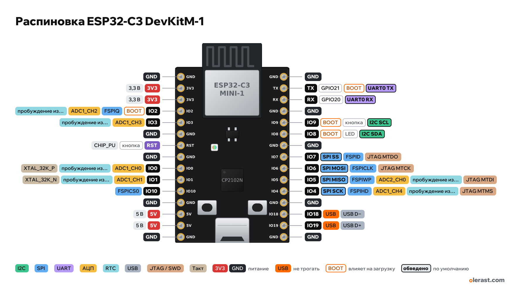
ESP32-C3 DevKitM-1 pinout
ESP32-C3-DevKitM-1, ESP32-C3, 3.3 V logic, 25.4×38.91 mm, 30 pins
verified17.10.2026
Top view, USB at the bottom, module antenna at the top.
CompareDownload PNG- Chip
- ESP32-C3, ESP32-C3-MINI-1 (4 MB flash in the package)
- Logic
- 3.3 V
- Power
- Micro-USB (CP2102N) 4.75-5.25 V5V 4.75-5.25 V3V3 3-3.6 V
- Defaults in arduino-esp32 (ESP32C3 Dev Module)
- I2C: SDA 8, SCL 9SPI: MOSI 6, MISO 5, SCK 4, SS 7UART: TX 21, RX 20
Which ESP32-C3 DevKitM-1 pins are safe to use
Free to use
GPIO0, GPIO1, GPIO3-7, GPIO10, GPIO20
Use with care
- GPIO2, GPIO8, GPIO9: strapping: the level at power-up selects the boot mode.
- GPIO18, GPIO19: USB lines: use them and you lose USB flashing and the serial port.
- GPIO21: signal at boot.
Important
- 3.3 V logic, don't put 5 V on the GPIO.
- Strapping pins: IO2, IO8 (RGB LED), IO9 (Boot button). Do not pull IO8 and IO2 to Ground at power-up.
- ADC: GPIO0-4 (ADC1). ADC2 (GPIO5) gives wrong readings per the ESP32-C3 errata, do not use it.
- IO18 and IO19 are the chip's built-in USB Serial/JTAG (not routed to the connector on this board, the pins are free, but using them removes JTAG over USB).
- Small components are drawn approximately; pins, module and board follow the dimensional drawing.
- Power it one way only: USB, 5V or 3V3.
All pins
| Label | Number | Functions | Limits | Check |
|---|---|---|---|---|
| GND | Ground | verified | ||
| 3V3 | 3.3 V | power inputpower output | verified | |
| 3V3 | 3.3 V | power inputpower output | verified | |
| IO2 | GPIO2 | interruptPWM (LEDC)ADC1_CH2wake from deep sleep (deep sleep GPIO)FSPIQ | not 5 V tolerantaffects boot (strapping) | verifiedStrapping: floating by default, Espressif recommends a pull-up. Do not pull low at reset. |
| IO3 | GPIO3 | interruptPWM (LEDC)ADC1_CH3wake from deep sleep (deep sleep GPIO) | not 5 V tolerant | verified |
| GND | Ground | verified | ||
| RST | CHIP_PU: enable and reset (low = reset) | onboard pull-uponboard button | verifiedRESET button on the board. | |
| GND | Ground | verified | ||
| IO0 | GPIO0 | interruptPWM (LEDC)ADC1_CH0wake from deep sleep (deep sleep GPIO)XTAL_32K_P | not 5 V tolerant | verified |
| IO1 | GPIO1 | interruptPWM (LEDC)ADC1_CH1wake from deep sleep (deep sleep GPIO)XTAL_32K_N | not 5 V tolerant | verified |
| IO10 | GPIO10 | interruptPWM (LEDC)FSPICS0 | not 5 V tolerant | verified |
| GND | Ground | verified | ||
| 5V | 5 V | power inputpower output | verified | |
| 5V | 5 V | power inputpower output | verified | |
| GND | Ground | verified | ||
| GND | Ground | verified | ||
| TX | GPIO21 | interruptPWM (LEDC)UART0 TX | not 5 V tolerantoutputs a signal at boot | verifiedConnected to the CP2102N: busy during flashing and Serial. |
| RX | GPIO20 | interruptPWM (LEDC)UART0 RX | not 5 V tolerant | verifiedConnected to the CP2102N: busy during flashing and Serial. |
| GND | Ground | verified | ||
| IO9 | GPIO9 | interruptPWM (LEDC)I2C SCL | not 5 V tolerantaffects boot (strapping)onboard button | verifiedStrapping: low at reset = firmware download mode (BOOT button). Internal pull-up.BOOT button on the board. |
| IO8 | GPIO8 | interruptPWM (LEDC)I2C SDA | not 5 V tolerantaffects boot (strapping)onboard LED | verifiedStrapping: must be high for firmware download mode (GPIO9 = 0), also controls ROM message output. Do not pull low at reset.Addressable RGB LED SK68XXMINI-HS on the board. |
| GND | Ground | verified | ||
| IO7 | GPIO7 | interruptPWM (LEDC)JTAG MTDOFSPIDSPI SS | not 5 V tolerant | verifiedJTAG pins: JTAG goes over USB by default, so these pins are free. |
| IO6 | GPIO6 | interruptPWM (LEDC)JTAG MTCKFSPICLKSPI MOSI | not 5 V tolerant | verifiedJTAG pins: JTAG goes over USB by default, so these pins are free. |
| IO5 | GPIO5 | interruptPWM (LEDC)ADC2_CH0wake from deep sleep (deep sleep GPIO)JTAG MTDIFSPIWPSPI MISO | not 5 V tolerantADC2 doesn't work with Wi-Fi on | verifiedADC2 on the ESP32-C3 gives wrong results per the errata, ESP-IDF does not recommend it. For the ADC use GPIO0–4.JTAG pins: JTAG goes over USB by default, so these pins are free. |
| IO4 | GPIO4 | interruptPWM (LEDC)ADC1_CH4wake from deep sleep (deep sleep GPIO)JTAG MTMSFSPIHDSPI SCK | not 5 V tolerant | verifiedJTAG pins: JTAG goes over USB by default, so these pins are free. |
| GND | Ground | verified | ||
| IO18 | GPIO18 | interruptPWM (LEDC)USB D− | not 5 V tolerantUSB line | verifiedBuilt-in USB Serial/JTAG line. If you use it as a GPIO, the port and flashing over USB disappear. |
| IO19 | GPIO19 | interruptPWM (LEDC)USB D+ | not 5 V tolerantUSB line | verifiedBuilt-in USB Serial/JTAG line. If you use it as a GPIO, the port and flashing over USB disappear. |
| GND | Ground | verified |
Sources
Every pin is verified against the manufacturer's documents.
- ESP32-C3-DevKitM-1 User Guide (Espressif), Header Block J1/J3user guide, checked 17.10.2026functions of all 30 pins of J1 and J3, RGB LED on GPIO8, Boot and Reset buttons, USB-UART bridge
- ESP32-C3-DevKitM-1 V1 dimensions (PDF, 2020-09-15)board drawing, checked 17.10.2026board 25.40×38.91 mm, rows 22.86 mm apart, 2.54 pitch, first pin about 2.06 mm from the top edge, module 13.2 mm overhangs the edge by 5.4 mm
- ESP32-C3-DevKitM-1 V1 schematic (2020-09-15)schematic, checked 17.10.2026CP2102N, SGM2212-3.3, SK68XXMINI-HS, ESP32-C3-MINI-1
- ESP32-C3 Series Datasheet (Espressif)datasheet, checked 15.10.2026pin functions, ADC1_CH0–4 on GPIO0–4, ADC2_CH0 on GPIO5, strapping GPIO2/8/9, USB D−/D+ on GPIO18/19, UART0 on GPIO20/21, JTAG GPIO4–7
- ESP-IDF: GPIO (ESP32-C3)user guide, checked 15.10.2026GPIO12–17 used by SPI flash, strapping pins, GPIO18/19 USB, deep sleep wake-up on GPIO0–5
- arduino-esp32: variants/esp32c3 and nologo_esp32c3_super_mini/pins_arduino.hArduino core, checked 15.10.2026defaults: TX 21, RX 20, SDA 8, SCL 9, SS 7, MOSI 6, MISO 5, SCK 4, LED_BUILTIN 8 (SuperMini)
- ESP32-C3 Series SoC Erratachip errata, checked 15.10.2026ADC2 may give wrong results
Size: from the Espressif V1 dimensional drawing (2020-09-15).
FAQ
- Which ESP32-C3 DevKitM-1 pins are I2C, SPI and UART?
- By default in arduino-esp32 (ESP32C3 Dev Module): I2C: SDA GPIO8, SCL GPIO9; SPI: MOSI GPIO6, MISO GPIO5, SCK GPIO4, SS GPIO7; UART: TX GPIO21, RX GPIO20.
- Which pin is the ESP32-C3 DevKitM-1 LED on?
- RGB LED SK68XXMINI-HS on GPIO8.
- Are the ESP32-C3 DevKitM-1 pins 5 V tolerant?
- No. The logic is 3.3 V and the pins are not 5 V tolerant: use a divider or a level shifter for 5 V signals.
- Does ADC2 on the ESP32-C3 DevKitM-1 work with Wi-Fi on?
- No. ADC2 pins (GPIO5) can't read analog while Wi-Fi is on. With Wi-Fi, use GPIO0-4 for the ADC.
You might also need
Similar boards
Next
- Emotion keychainmy ESP32-C3 project, prototype
- ESP32 music playermy ESP32 project, prototype
- DITHR//CAMmy ESP32 project, prototype
Need firmware or a device built on ESP32? I'll build it to order