1-channel 5 V relay module with optocoupler pinout
1-channel 5 V relay module with optocoupler (active LOW, JD-VCC jumper), Songle SRD-05VDC-SL-C relay + PC817 optocoupler, 5 V logic, 50×26 mm, 8 pins
partly verified15.10.2026
Top view, control on the left, terminal block on the right.
Download PNG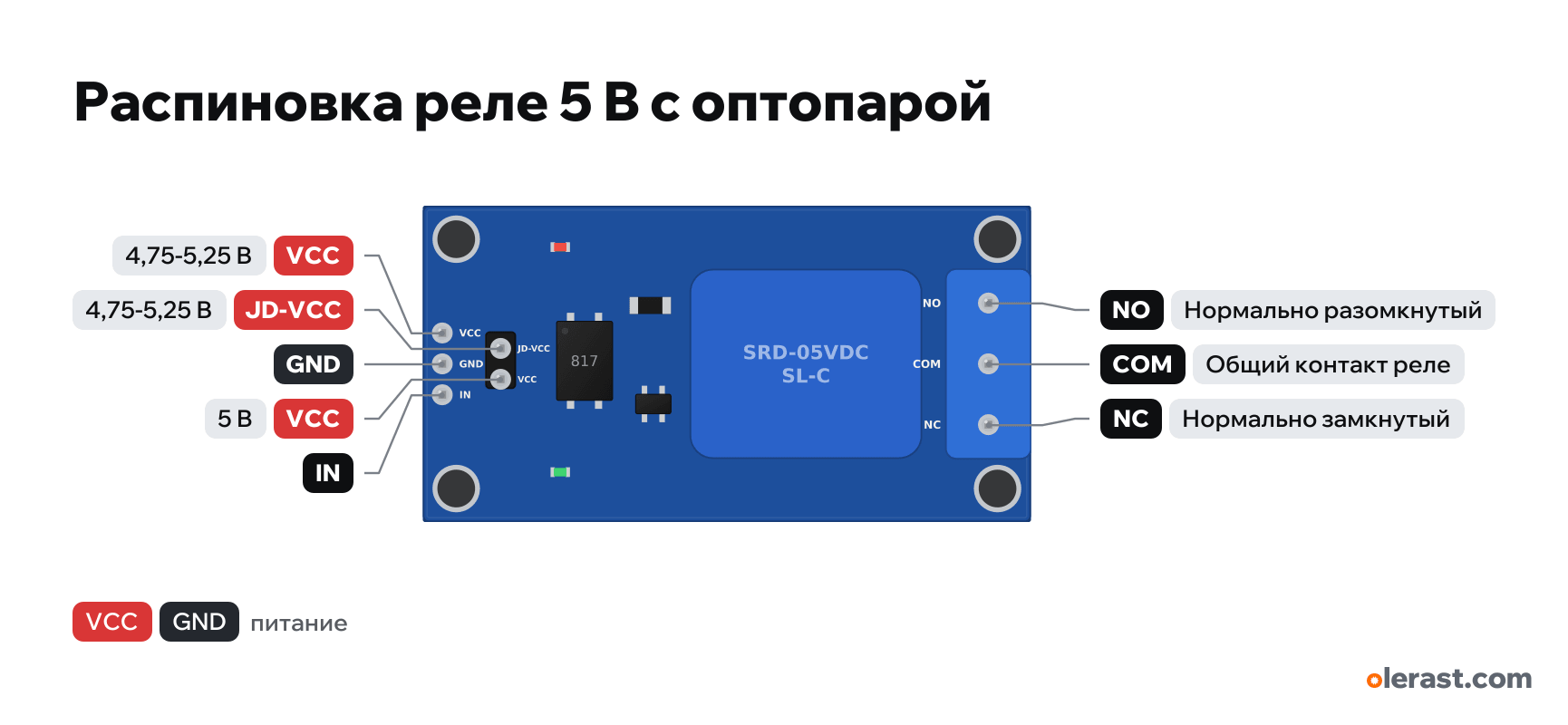
- Chip
- Songle SRD-05VDC-SL-C relay + PC817 optocoupler
- Logic
- 5 V
- Power
- VCC 4.75-5.25 VJD-VCC 4.75-5.25 V
Important
- The relay turns on with a low level on IN (LOW). Set HIGH right at program start.
- JD-VCC ↔ VCC jumper fitted: the coil is powered from the same VCC. Remove it for isolation from the MCU or for a 3.3 V MCU (VCC = 3.3 V, JD-VCC = 5 V).
- The coil draws about 70 mA: an Arduino USB port can drive 1-2 relays, more needs a separate 5 V source.
- 220 V mains on the terminal block is lethally dangerous: the module has no enclosure and the trace spacing is small. Keep the contact current under 5 A.
- Geometry from third-party KiCad footprints and seller descriptions (±0.5 mm), small components are drawn approximately. Check with calipers before laying out your own board.
- For full isolation: remove the jumper, VCC from the microcontroller, JD-VCC and a separate coil ground from another 5 V source.
Revisions and clones
- Without an optocoupler (KY-019 and similar): pins S, +, −, active HIGH, a separate entry relay-module-1ch-5v-ky019.
- Some boards have an H/L jumper (trigger level is selectable): then a low level works only in the L position.
- A high-power 30 A version: 50×33 mm board, a different relay.
All pins
| Label | Number | Functions | Limits | Check |
|---|---|---|---|---|
| VCC | 5 V | power input | not from manufacturerNo-name module: the order of the control pins (VCC, GND, IN or DC+, DC−, IN) differs between batches, check the labels. Geometry from the PCBWay description, no footprint.Labelled on other revisions as: DC+, + | |
| GND | Ground | not from manufacturerNo-name module: the order of the control pins (VCC, GND, IN or DC+, DC−, IN) differs between batches, check the labels. Geometry from the PCBWay description, no footprint.Labelled on other revisions as: DC-, - | ||
| IN | not from manufacturerNo-name module: the order of the control pins (VCC, GND, IN or DC+, DC−, IN) differs between batches, check the labels. Geometry from the PCBWay description, no footprint.Active level is LOW: digitalWrite(pin, LOW) turns the relay on. Set HIGH at startup, otherwise the relay will click.With a 3.3 V MCU (ESP32, ESP8266, Pico) and VCC = 5 V, a 3.3 V high level may not turn the relay off. Fix: VCC = 3.3 V and JD-VCC = 5 V with the jumper removed, or a transistor.Labelled on other revisions as: IN1, S | |||
| JD-VCC | 5 V | power input | not verifiedSome 1-channel boards have no JD-VCC jumper (it is typical for 2-, 4-, 8-channel boards), and some have an H/L level select jumper instead. The position is drawn schematically.Labelled on other revisions as: JD+ | |
| VCC | 5 V | power inputpower output | not verifiedThe jumper position is drawn schematically; some boards do not have it. | |
| NO | Normally open: closes with COM when the relay turns on | not verifiedCOM is always in the middle, while NO and NC at the edges are placed differently on different boards. Check the labels at the terminal block (or buzz it out: NC is connected to COM while the relay is off). | ||
| COM | Relay common contact | not from manufacturerNo-name module: the order of the control pins (VCC, GND, IN or DC+, DC−, IN) differs between batches, check the labels. Geometry from the PCBWay description, no footprint.Up to 10 A 250 V~ / 10 A 30 V= per the relay datasheet; the module traces and terminal block are usually not rated for that current. | ||
| NC | Normally closed: connected to COM while the relay is off | not verifiedCOM is always in the middle, while NO and NC at the edges are placed differently on different boards. Check the labels at the terminal block (or buzz it out: NC is connected to COM while the relay is off). |
Sources
Not verified against the manufacturer: 8 of 8 pins. The pin card says what confirms each one and where sources disagree.
- Songle SRD series relay datasheetdatasheet, checked 15.10.2026SRD-05VDC-SL-C: 5 V coil, 70 Ω, 71.4 mA, 0.36 W; SPDT contacts 10 A 250 V~ / 10 A 30 V=; pull-in at no more than 75% of rated voltage
- LastMinuteEngineers: One channel relay module with Arduinothird-party source, checked 15.10.2026VCC, GND, IN, active-LOW input, coil current about 70 mA, diode on the coil, NC, COM, NO contacts 10 A 250 V~ / 30 V=
- PCBWay: 1 channel relay module 5V with optocoupler (high/low trigger)third-party source, checked 15.10.202650×26×18.5 mm, Ø3.1 holes at 44.5×20.5, DC+, DC−, IN, H/L jumper
- Makerlab: 1 channel relay module with optocouplerthird-party source, checked 15.10.2026jumper between DC+ (VCC) and JD+ (JD-VCC)
- Universal-Solder: troubleshooting ESP32 relay problemsthird-party source, checked 15.10.2026with VCC 5 V a 3.3 V output does not turn off the optocoupler LED; fix: separate supply through JD-VCC or a transistor
Size: 50×26×18.5 mm, Ø3.1 holes at 44.5×20.5 mm (PCBWay); differs in other batches (approximate).
FAQ
- What supply voltage does the 1-channel 5 V relay module with optocoupler need?
- VCC: 4.75-5.25 V; JD-VCC: 4.75-5.25 V. 5 V logic.
You might also need
Similar boards
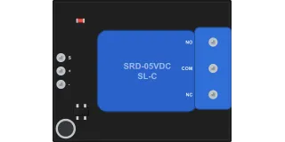
1-channel 5 V relay module without optocoupler (KY-019, triggers on HIGH)
Songle SRD-05VDC-SL-C relay6 pins
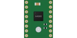
A4988 stepper motor driver (StepStick, Pololu and clones)
Allegro A498816 pins
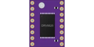
DRV8825 stepper motor driver (StepStick, Pololu and clones)
TI DRV882516 pins
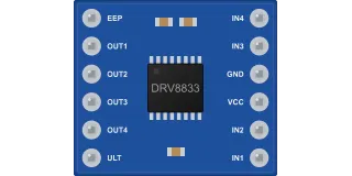
DRV8833, dual motor driver (HW-627 module, 12 pins)
TI DRV883312 pins