DRV8825 stepper motor driver pinout
DRV8825 stepper motor driver (StepStick, Pololu and clones), TI DRV8825, 5 V logic, 15.24×20.32 mm, 16 pins
verified20.10.2026
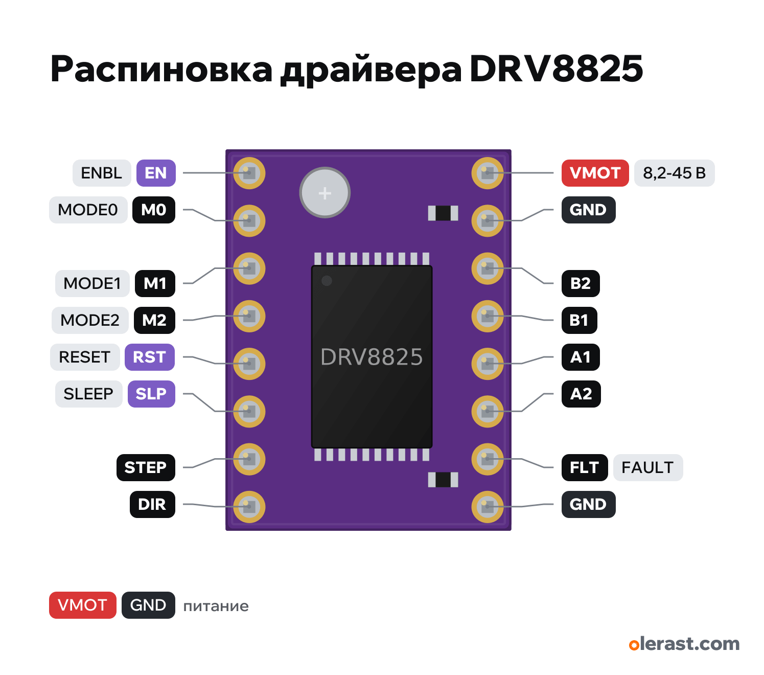
Component side view, trimmer at the top next to EN: logic on the left (EN at the top, DIR at the bottom), power and motor on the right (VMOT at the top).
Download PNG- Chip
- TI DRV8825
- Logic
- 5 V
- Power
- VMOT 8.2-45 V
Important
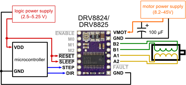
- Minimal wiring (Pololu): VMOT and GND from the 8.2-45 V supply with a 47-100 µF electrolytic, RST and SLP to the 3.3-5 V logic supply, STEP and DIR to GPIO, logic GND to the microcontroller GND.
- Microstepping M0, M1, M2: 000 full step, 100 half step, 010 1/4, 110 1/8, 001 1/16, 101, 011 and 111 1/32 (1 = HIGH).
- Current: I = Vref × 2 with Rsense 0.1 Ω (Vref = I / 2).
- The motor current is set by the trimmer potentiometer: the Vref voltage on its wiper. The Vref calculator on the site works out the setting for your motor (Tools, "Vref calculator").
- On the DRV8825, Vref appears only when VMOT is applied and RST and SLP are high.
- It fits an A4988 socket, but where the A4988 has VDD, the DRV8825 has the FLT pin: the board feeds 5 V there, which is acceptable (1.5 kΩ resistor on the board).
- About 1.5 A per phase without a heatsink, up to 2.2 A with a heatsink and airflow (Pololu).
- There is no separate logic supply: the inputs accept both 3.3 V and 5 V (high level from 2.2 V).
Revisions and clones
- DRV8825 clones (often purple too): the trimmer may be at the other edge, labels are on the back.
- Pololu DRV8824: same header, current up to 0.75 A.
All pins
| Label | Number | Functions | Limits | Check |
|---|---|---|---|---|
| EN | ENBL: LOW enables the outputs, HIGH disables them; 100 kΩ pull-down to ground | onboard pull-down | verifiedCan be left unconnected: pulled to ground inside, the outputs are enabled (Pololu).Labelled on other revisions as: ENBL, ENABLE, EN# | |
| M0 | MODE0: microstep select | verifiedWith M0-M2 unconnected: full step. 1/32: M0 and M2 HIGH.Labelled on other revisions as: MODE0, MS1 | ||
| M1 | MODE1: microstep select | verifiedLabelled on other revisions as: MODE1, MS2 | ||
| M2 | MODE2: microstep select | verifiedLabelled on other revisions as: MODE2, MS3 | ||
| RST | RESET: LOW resets; 100 kΩ pull-down to ground, must be pulled high | verifiedPulled to ground inside: without HIGH the driver doesn't work. Tie it to the 3.3-5 V logic supply or a GPIO.Labelled on other revisions as: RESET, RST# | ||
| SLP | SLEEP: LOW puts it to sleep; 1 MΩ pull-down to ground, must be pulled high | verifiedPulled to ground inside: without HIGH the driver sleeps. An external pull-up of 4.7 kΩ or less (Pololu).Labelled on other revisions as: SLEEP, SLP# | ||
| STEP | STEP: a LOW→HIGH edge makes one (micro)step | verifiedLabelled on other revisions as: STP | ||
| DIR | DIR: rotation direction | verified | ||
| VMOT | 12 V | power input | verifiedElectrolytic capacitor of 47 µF or more between VMOT and GND right at the board (Pololu).Labelled on other revisions as: VM | |
| GND | Ground | verifiedMotor power ground. | ||
| B2 | B2: coil B, second terminal | verifiedOutput to the motor winding, motor supply voltage. Don't connect to GPIO or logic.Labelled on other revisions as: 2B, BOUT2 | ||
| B1 | B1: coil B, first terminal | verifiedOutput to the motor winding, motor supply voltage. Don't connect to GPIO or logic.Labelled on other revisions as: 2A, BOUT1 | ||
| A1 | A1: coil A, first terminal | verifiedOutput to the motor winding, motor supply voltage. Don't connect to GPIO or logic.Labelled on other revisions as: 1A, AOUT1 | ||
| A2 | A2: coil A, second terminal | verifiedOutput to the motor winding, motor supply voltage. Don't connect to GPIO or logic.Labelled on other revisions as: 1B, AOUT2 | ||
| FLT | FAULT: LOW on overtemperature or overload (open drain through 1.5 kΩ) | verifiedSits where VDD is on the A4988. It can be tied to the logic supply through 1.5 kΩ: on a board made for the A4988 it pulls SLEEP up through 10 kΩ (Pololu).Labelled on other revisions as: FAULT, nFAULT | ||
| GND | Ground | verifiedLogic ground, shared with the microcontroller. |
Sources
Every pin is verified against the manufacturer's documents.
- Pololu: DRV8825 Stepper Motor Driver Carrier, High Current (#2133)user guide, checked 20.10.2026VMOT 8.2-45 V; logic 2.2-5.25 V on RESET and SLEEP, no separate logic supply needed; electrolytic capacitor of 47 µF or more on VMOT; FAULT: 10 kΩ to SLEEP and 1.5 kΩ in series, can be tied to the logic supply (where VDD is on the A4988); SLEEP to ground 1 MΩ, RESET to ground 100 kΩ, both must be pulled high; ENBL to ground 100 kΩ, can be left unconnected; MODE0-MODE2 table up to 1/32; Rsense 0.1 Ω, current = Vref × 2
- Pololu: DRV8825 carrier with dimensions (photo of the back side with labels)board drawing, checked 20.10.20260.6×0.8 inch; on the back: VMOT, GND, B2, B1, A1, A2, FLT, GND in one row and EN, M0, M1, M2, RST, SLP, STEP, DIR in the other
- Pololu: minimal wiring diagram DRV8824/DRV8825manufacturer pinout, checked 20.10.2026top view: trimmer next to the ENABLE pin; RESET and SLEEP to the logic supply; 100 µF electrolytic on VMOT
Size: 0.6×0.8 in (15.24×20.32 mm), rows 12.7 mm (0.5 in) apart, 2.54 mm pitch.
FAQ
- What supply voltage does the DRV8825 stepper motor driver need?
- VMOT: 8.2-45 V. 5 V logic.