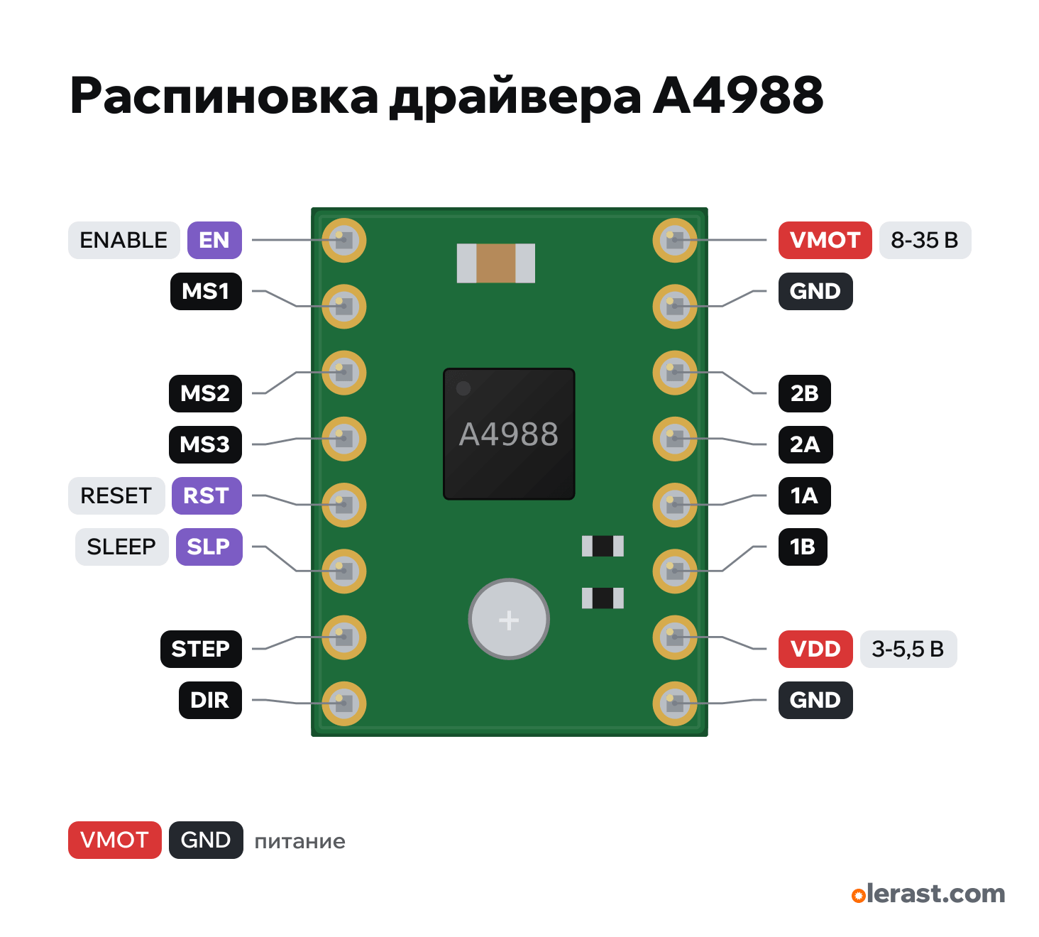
A4988 stepper motor driver pinout
A4988 stepper motor driver (StepStick, Pololu and clones), Allegro A4988, 5 V logic, 15.24×20.32 mm, 16 pins
verified20.10.2026
Component side view, trimmer at the bottom: logic on the left (EN at the top, DIR at the bottom), power and motor on the right (VMOT at the top).
Download PNG- Chip
- Allegro A4988
- Logic
- 5 V
- Power
- VMOT 8-35 VVDD 3-5.5 V
Important
- Minimal wiring (Pololu): VMOT and GND from the 8-35 V motor supply with a 47-100 µF electrolytic, VDD and GND from the logic, STEP and DIR to GPIO, RST tied to SLP, coils to 1A-1B and 2A-2B.
- Microstepping MS1, MS2, MS3: 000 full step, 100 half step, 010 1/4, 110 1/8, 111 1/16 (1 = HIGH).
- Current: I = Vref / (8 × R_CS). R_CS is 0.068 Ω on Pololu, on red clones usually R100 (0.1 Ω) or R200 (0.2 Ω): see the marking on the resistors next to the chip.
- The motor current is set by the trimmer potentiometer: the Vref voltage on its wiper. The Vref calculator on the site works out the setting for your motor (Tools, "Vref calculator").
- Find the coils with a continuity test: the two wires of one coil beep to each other (a few ohms). One coil goes to 1A and 1B, the other to 2A and 2B.
- Don't connect or disconnect the motor while VMOT is powered: the spike burns out the driver.
- About 1 A per phase without a heatsink, up to 2 A with a heatsink and airflow (Pololu).
- The logic draws up to 8 mA. Motor current flows only through VMOT.
Revisions and clones
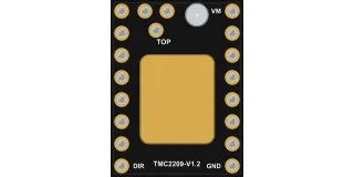
- Red clones (StepStick): same pins, R_CS 0.1 or 0.2 Ω, the trimmer may be at the other edge. Labels are on the back.
- Pololu Black Edition (#2128): four-layer board, same pins, handles more current.
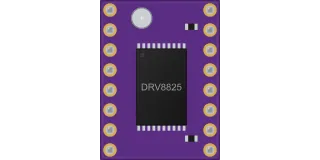
- DRV8825 (drv8825-module): same header, but the FLT pin sits where VDD is, and microstepping goes up to 1/32.
All pins
| Label | Number | Functions | Limits | Check |
|---|---|---|---|---|
| EN | ENABLE: LOW enables the outputs, HIGH disables them (motor free) | onboard pull-down | verifiedPulled to ground by 100 kΩ on the Pololu board: left unconnected, the outputs are enabled.Labelled on other revisions as: ENABLE, EN# | |
| MS1 | MS1: microstep select (100 kΩ pull-down to ground inside) | verifiedWith MS1-MS3 unconnected: full step. 1/16 step: all three to VDD. | ||
| MS2 | MS2: microstep select (50 kΩ pull-down to ground inside) | verified | ||
| MS3 | MS3: microstep select (100 kΩ pull-down to ground inside) | verified | ||
| RST | RESET: LOW resets the driver; no pull-up, don't leave it floating | verifiedThe pin floats: tie it to the neighboring SLP (as Pololu advises) or drive it HIGH.Labelled on other revisions as: RESET, RST# | ||
| SLP | SLEEP: LOW puts the driver to sleep; 100 kΩ pull-up to VDD on the board | onboard pull-up | verifiedLabelled on other revisions as: SLEEP, SLP# | |
| STEP | STEP: a LOW→HIGH edge makes one (micro)step | verifiedLabelled on other revisions as: STP | ||
| DIR | DIR: rotation direction | verified | ||
| VMOT | 12 V | power input | verifiedElectrolytic capacitor of 47 µF or more between VMOT and GND right at the board: without it the power-up spike destroys the driver (Pololu).Labelled on other revisions as: VM, VBB | |
| GND | Ground | verifiedMotor power ground. | ||
| 2B | 2B: coil 2, second terminal | verifiedOutput to the motor winding, motor supply voltage. Don't connect to GPIO or logic.Labelled on other revisions as: B2, OUT2B | ||
| 2A | 2A: coil 2, first terminal | verifiedOutput to the motor winding, motor supply voltage. Don't connect to GPIO or logic.Labelled on other revisions as: A2, OUT2A | ||
| 1A | 1A: coil 1, first terminal | verifiedOutput to the motor winding, motor supply voltage. Don't connect to GPIO or logic.Labelled on other revisions as: A1, OUT1A | ||
| 1B | 1B: coil 1, second terminal | verifiedOutput to the motor winding, motor supply voltage. Don't connect to GPIO or logic.Labelled on other revisions as: B1, OUT1B | ||
| VDD | 5 V | power input | verifiedLogic supply 3-5.5 V. The input high level starts at 0.7 × VDD: at VDD 5 V that is 3.5 V, so 3.3 V signals from an ESP32 may not be enough. With an ESP32, power VDD from 3.3 V. | |
| GND | Ground | verifiedLogic ground, shared with the microcontroller. |
Sources
Every pin is verified against the manufacturer's documents.
- Pololu: A4988 Stepper Motor Driver Carrier (#1182)user guide, checked 20.10.2026VMOT 8-35 V, VDD 3-5.5 V; electrolytic capacitor of 47 µF or more between VMOT and GND at the board; MS1-MS3 table (full step, 1/2, 1/4, 1/8, 1/16); pull-downs to ground: MS1 and MS3 100 kΩ, MS2 50 kΩ; RST floats, tie it to the neighboring SLP if needed; R_CS 0.068 Ω (since 2017), 0.05 Ω (older green boards); I = Vref / (8 × R_CS)
- Pololu: A4983/A4988 carrier with dimensions (photo of the back side with labels)board drawing, checked 20.10.20260.6×0.8 inch; on the back: VMOT, GND, 2B, 2A, 1A, 1B, VDD, GND in one row and EN, MS1, MS2, MS3, RST, SLP, STEP, DIR in the other
- Pololu: A4988 carrier schematic (green and black edition)schematic, checked 20.10.2026SLEEP is pulled up to VDD by 100 kΩ (R3), ENABLE is pulled down to ground by 100 kΩ (R6), RESET has no pull; 10 kΩ trimmer with 20 kΩ from VDD to VREF; OUT1B, OUT1A, OUT2A, OUT2B go to 1B, 1A, 2A, 2B
- Allegro A4988 DMOS Microstepping Driver with Translator (Pololu copy, rev. 4)datasheet, checked 20.10.2026VBB 8-35 V; VDD 3.0-5.5 V; logic input: high level from 0.7 × VDD, low level up to 0.3 × VDD, up to 5.5 V; logic current up to 8 mA; output current up to 2 A
Size: 0.6×0.8 in (15.24×20.32 mm), rows 12.7 mm (0.5 in) apart, 2.54 mm pitch.
FAQ
- What supply voltage does the A4988 stepper motor driver need?
- VMOT: 8-35 V; VDD: 3-5.5 V. 5 V logic.