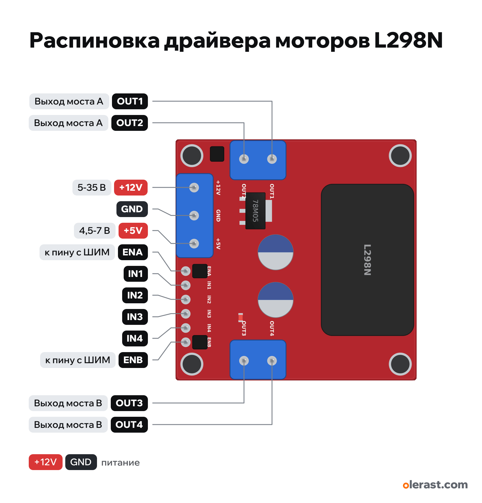
L298N motor driver pinout
L298N motor driver (red module with heatsink), ST L298N, 5 V logic, 43×43 mm, 13 pins
partly verified15.10.2026
Top view, heatsink on top, motor terminals on the sides, power and control at the bottom, rotated 90° on the diagram.
Download PNG- Chip
- ST L298N
- Logic
- 5 V
- Power
- +12V (motor supply) 5-35 V+5V 4.5-7 V
Important
- The L298 is a bipolar bridge: it loses about 2 V and gets hot. For 3-6 V motors and currents above 1 A, a TB6612FNG or DRV8833 is better.
- 5V-EN jumper: fitted, the on-board 78M05 powers the logic and gives 5 V on the +5V terminal; above 12 V supply remove it and feed 5 V to +5V separately.
- The ENA and ENB jumpers are fitted: motors are always enabled at full speed. For speed control, remove them and apply PWM to ENA/ENB.
- The module ground and the microcontroller ground must be common.
- IN1-IN4 control: 10 = forward, 01 = reverse, 00 or 11 = stop (11 with ENA=1 is braking).
- Geometry from third-party KiCad footprints and seller descriptions (±0.5 mm), small components are drawn approximately. Check with calipers before laying out your own board.
- Do not feed external 5 V to +5V while the 5V-EN jumper is fitted.
- The 78M05 needs at least 7 V at its input: with 5-6 V on +12V the +5V output does not hold.
Revisions and clones
- Similar 54×44 mm modules exist with a 2×4 header (IN1-IN4, ENA, 5V, 5V, ENB): different layout, check the labels.
- The power terminal order is sometimes described as "+5V, GND, +12V": it is the same terminal block read from the other side. Check the silkscreen.
All pins
| Label | Number | Functions | Limits | Check |
|---|---|---|---|---|
| OUT1 | Bridge A output (motor A) | not from manufacturerWhich pin is OUT1 and which is OUT2 follows the Handsontec numbering (around the board) and was not checked against a photo. For a motor this only changes the rotation direction. | ||
| OUT2 | Bridge A output (motor A) | not from manufacturerWhich pin is OUT1 and which is OUT2 follows the Handsontec numbering (around the board) and was not checked against a photo. | ||
| OUT3 | Bridge B output (motor B) | not from manufacturerThe OUT3/OUT4 order follows the Handsontec numbering (around the board) and was not checked against a photo. | ||
| OUT4 | Bridge B output (motor B) | not from manufacturerThe OUT3/OUT4 order follows the Handsontec numbering (around the board) and was not checked against a photo. | ||
| +12V | 12 V | power input | not from manufacturerNo-name module: order from Handsontec, Random Nerd Tutorials and LastMinuteEngineers (they agree), coordinates from KiCad footprints (they differ from each other by up to 1.5 mm).Motor supply. The L298 bridge drops about 2 V (1.8 V typ. at 1 A, up to 4.9 V at 2 A): a 6 V motor needs about 8 V.Labelled on other revisions as: VCC, VS, 12V | |
| GND | Ground | not from manufacturerNo-name module: order from Handsontec, Random Nerd Tutorials and LastMinuteEngineers (they agree), coordinates from KiCad footprints (they differ from each other by up to 1.5 mm).Common ground: connect to the microcontroller GND. | ||
| +5V | 5 V | power inputpower output | not from manufacturerNo-name module: order from Handsontec, Random Nerd Tutorials and LastMinuteEngineers (they agree), coordinates from KiCad footprints (they differ from each other by up to 1.5 mm).With the 5V-EN jumper: the 78M05 output (can power an Arduino, up to ~0.5 A). Without the jumper: 5 V input for the L298 logic.Labelled on other revisions as: 5V | |
| ENA | ENA: bridge A enable, PWM = speed | onboard pull-up | not from manufacturerNo-name module: order from Handsontec, Random Nerd Tutorials and LastMinuteEngineers (they agree), coordinates from KiCad footprints (they differ from each other by up to 1.5 mm).A jumper to 5 V is fitted at the factory: motor A is always enabled, full speed. To control speed, remove the jumper and apply PWM. | |
| IN1 | not from manufacturerNo-name module: order from Handsontec, Random Nerd Tutorials and LastMinuteEngineers (they agree), coordinates from KiCad footprints (they differ from each other by up to 1.5 mm).Logic high threshold is about 2.3 V: 3.3 V logic (ESP32, Pico) works. | |||
| IN2 | not from manufacturerNo-name module: order from Handsontec, Random Nerd Tutorials and LastMinuteEngineers (they agree), coordinates from KiCad footprints (they differ from each other by up to 1.5 mm). | |||
| IN3 | not from manufacturerNo-name module: order from Handsontec, Random Nerd Tutorials and LastMinuteEngineers (they agree), coordinates from KiCad footprints (they differ from each other by up to 1.5 mm). | |||
| IN4 | not from manufacturerNo-name module: order from Handsontec, Random Nerd Tutorials and LastMinuteEngineers (they agree), coordinates from KiCad footprints (they differ from each other by up to 1.5 mm). | |||
| ENB | ENB: bridge B enable, PWM = speed | onboard pull-up | not from manufacturerNo-name module: order from Handsontec, Random Nerd Tutorials and LastMinuteEngineers (they agree), coordinates from KiCad footprints (they differ from each other by up to 1.5 mm).A jumper to 5 V is fitted at the factory. Remove it for PWM. |
Sources
Not verified against the manufacturer: 13 of 13 pins. The pin card says what confirms each one and where sources disagree.
- ST L298 Dual Full-Bridge Driver datasheetdatasheet, checked 15.10.2026Vs up to 46 V, 2 A per channel (3 A peak), drop 1.8 V typ. / 3.2 V max at 1 A, 4.9 V max at 2 A (checked against the NUS copy)
- Handsontec L298N Dual H-Bridge Motor Driver (MDU-1049), copythird-party source, checked 15.10.202614 points around the board: OUT1/OUT2, 5V-EN, +12V, GND, +5V, ENA, IN1-IN4, ENB, OUT3/OUT4; logic high threshold 2.3 V
- LastMinuteEngineers: L298N motor driver tutorialthird-party source, checked 15.10.2026drop about 2 V, 2 A per channel, 5 V output up to 0.5 A, remove the 5V-EN jumper above 12 V, ENA/ENB jumpers
- Random Nerd Tutorials: ESP32 with DC motor and L298Nthird-party source, checked 15.10.2026power terminal order +12V, GND, +5V; OUT1/OUT2 on the left; 3.3 V control
- KiCad: MetalMusings/MyOwnEtherCATDevice «L298N Motor driver module», stanleyseow/SVTmaker.pretty L298N-module-43x43mm, FABallemand/RC-Car L298N_modulethird-party source, checked 15.10.2026outline 43×43...43.4×43.8, terminal blocks at 5.0 mm pitch, 6-pin header at 2.54 pitch 2.2 mm from the bottom edge, holes 37 mm apart
Size: 43×43 mm for Keyestudio and Probots and in the SVTmaker footprint; 43.4×43.8 in another footprint; Handsontec lists 34×43 (approximate).
FAQ
- What supply voltage does the L298N motor driver need?
- +12V (motor supply): 5-35 V; +5V: 4.5-7 V. 5 V logic.