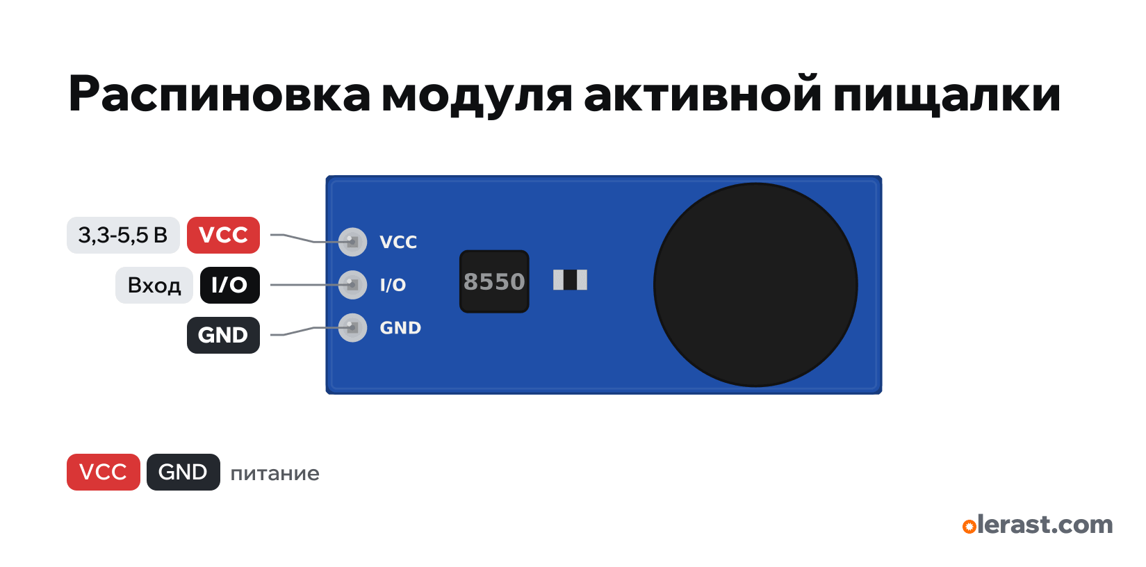
Buzzer module pinout
Buzzer module (VCC, I/O, GND, active low), Buzzer + S8550, 5 V logic, 33×13 mm, 3 pins
partly verified17.10.2026
Top view, header on the left.
Download PNG- Chip
- Buzzer + S8550
- Logic
- 5 V
- Power
- VCC 3.3-5.5 V
Important
- Active low: beeps with LOW on I/O. After reset an ESP32 pin is briefly high impedance: the module may chirp.
- At 3.3 V it is quieter; if VCC is 5 V and the logic is 3.3 V, the PNP may not turn fully off (quiet beep at HIGH): power the module from 3.3 V.
All pins
| Label | Number | Functions | Limits | Check |
|---|---|---|---|---|
| VCC | 5 V | power input | not from manufacturerCircuit and pin order are from sellers; there are active-high modules with an NPN (S8050) and the order S, +, −. | |
| I/O | not from manufacturerCircuit and pin order are from sellers; there are active-high modules with an NPN (S8050) and the order S, +, −.Active low: digitalWrite(pin, LOW) beeps, HIGH is silent.Labelled on other revisions as: IO, SIG, S | |||
| GND | Ground | not from manufacturerCircuit and pin order are from sellers; there are active-high modules with an NPN (S8050) and the order S, +, −. |
Sources
Not verified against the manufacturer: 3 of 3 pins. The pin card says what confirms each one and where sources disagree.
- onsemi SS8550 PNP (module circuit on the S8550)datasheet, checked 17.10.2026PNP switch: turns on when the base is below the emitter (VCC), i.e. with LOW on the input
- Handson Technology: Active Buzzer Module (low level trigger)third-party source, checked 17.10.2026pins VCC, I/O, GND; 3.3-5 V; LOW on I/O = sound
Size: about 33×13 mm, from a photo (approximate).
FAQ
- What supply voltage does the Buzzer module need?
- VCC: 3.3-5.5 V. 5 V logic.