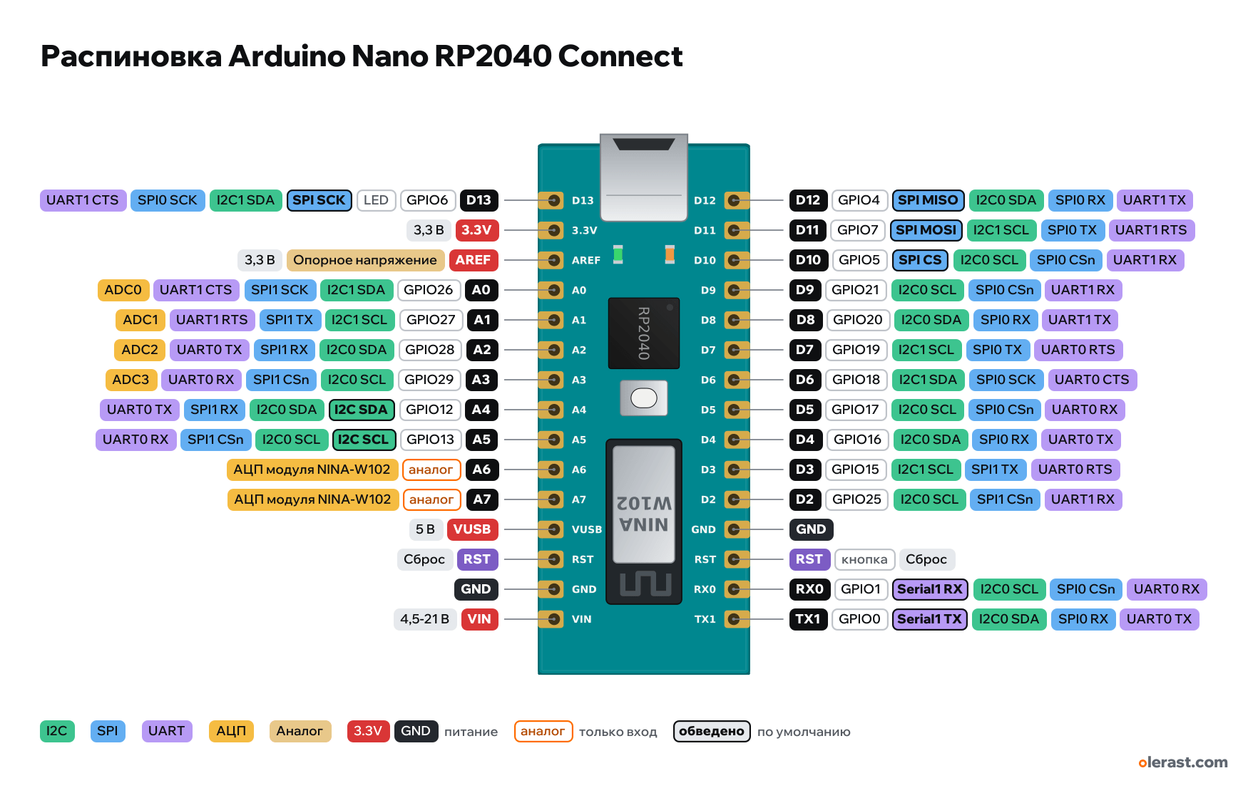
Arduino Nano RP2040 Connect pinout
Arduino Nano RP2040 Connect, RP2040, 3.3 V logic, 45×18 mm, 30 pins
verified17.10.2026
- D13GPIO613LEDSPI SCKI2C1 SDASPI0 SCKUART1 CTS
- 3.3V3.3 V
- AREFReference voltage3.3 V
- A0GPIO2614I2C1 SDASPI1 SCKUART1 CTSADC0
- A1GPIO2715I2C1 SCLSPI1 TXUART1 RTSADC1
- A2GPIO2816I2C0 SDASPI1 RXUART0 TXADC2
- A3GPIO2917I2C0 SCLSPI1 CSnUART0 RXADC3
- A4GPIO1218I2C SDAI2C0 SDASPI1 RXUART0 TX
- A5GPIO1319I2C SCLI2C0 SCLSPI1 CSnUART0 RX
- A6analogADC of the NINA-W102…
- A7analogADC of the NINA-W102…
- VUSB5 V
- RSTReset
- GND
- VIN4.5-21 V
- D12GPIO412SPI MISOI2C0 SDASPI0 RXUART1 TX
- D11GPIO711SPI MOSII2C1 SCLSPI0 TXUART1 RTS
- D10GPIO510SPI CSI2C0 SCLSPI0 CSnUART1 RX
- D9GPIO219I2C0 SCLSPI0 CSnUART1 RX
- D8GPIO208I2C0 SDASPI0 RXUART1 TX
- D7GPIO197I2C1 SCLSPI0 TXUART0 RTS
- D6GPIO186I2C1 SDASPI0 SCKUART0 CTS
- D5GPIO175I2C0 SCLSPI0 CSnUART0 RX
- D4GPIO164I2C0 SDASPI0 RXUART0 TX
- D3GPIO153I2C1 SCLSPI1 TXUART0 RTS
- D2GPIO252I2C0 SCLSPI1 CSnUART1 RX
- GND
- RSTbuttonReset
- RX0GPIO10Serial1 RXI2C0 SCLSPI0 CSnUART0 RX
- TX1GPIO01Serial1 TXI2C0 SDASPI0 RXUART0 TX
Top view, USB on the left (as on the official pinout), rotated 90° on the diagram.
CompareDownload PNG- Chip
- RP2040, u-blox NINA-W102 (Wi-Fi, Bluetooth)
- Logic
- 3.3 V
- Power
- Micro-USB 4.8-5.25 VVIN 4.5-21 V
- Defaults in ArduinoCore-mbed (NANO_RP2040_CONNECT)
- I2C: SDA 12, SCL 13SPI: MOSI 7, MISO 4, SCK 6, SS 5UART: TX 0, RX 1LED: 6
Which Arduino Nano RP2040 Connect pins are safe to use
Free to use
GPIO0, GPIO1, GPIO4, GPIO5, GPIO7, GPIO12, GPIO13, GPIO15-21, GPIO25-29
Use with care
- GPIO6: onboard LED.
- A6, A7: analog input only.
Important
- 3.3 V logic, don't apply 5 V to the pins.
- Sketch numbers are D0…D13, A0…A7 (Arduino mbed core), not RP2040 GPIO. In the arduino-pico core (Philhower) they are GPIO.
- A6 and A7 are only the NINA module ADC (through WiFiNINA), A4/A5 are also read through NINA.
- The "5V" pin here is VUSB and is not connected by default.
- I2C A4/A5 is already used by the LSM6DSOX IMU (0x6A) and ATECC608A (0x60).
- Pin rows follow 2.54 mm pitch and 0.6 in width; small components are drawn approximately.
All pins
| Label | Number | Functions | Limits | Check |
|---|---|---|---|---|
| D12 | GPIO4, Arduino 12 | interruptSPI0 RX (MISO)UART1 TXI2C0 SDAPWM 2APIO0, PIO1SPI MISO (SPI0 RX) | not 5 V tolerant | verified |
| D11 | GPIO7, Arduino 11 | interruptSPI0 TX (MOSI)UART1 RTSI2C1 SCLPWM 3BPIO0, PIO1SPI MOSI (SPI0 TX) | not 5 V tolerant | verified |
| D10 | GPIO5, Arduino 10 | interruptSPI0 CSnUART1 RXI2C0 SCLPWM 2BPIO0, PIO1SPI CS | not 5 V tolerant | verified |
| D9 | GPIO21, Arduino 9 | interruptSPI0 CSnUART1 RXI2C0 SCLPWM 2BPIO0, PIO1 | not 5 V tolerant | verified |
| D8 | GPIO20, Arduino 8 | interruptSPI0 RX (MISO)UART1 TXI2C0 SDAPWM 2APIO0, PIO1 | not 5 V tolerant | verified |
| D7 | GPIO19, Arduino 7 | interruptSPI0 TX (MOSI)UART0 RTSI2C1 SCLPWM 1BPIO0, PIO1 | not 5 V tolerant | verified |
| D6 | GPIO18, Arduino 6 | interruptSPI0 SCKUART0 CTSI2C1 SDAPWM 1APIO0, PIO1 | not 5 V tolerant | verified |
| D5 | GPIO17, Arduino 5 | interruptSPI0 CSnUART0 RXI2C0 SCLPWM 0BPIO0, PIO1 | not 5 V tolerant | verified |
| D4 | GPIO16, Arduino 4 | interruptSPI0 RX (MISO)UART0 TXI2C0 SDAPWM 0APIO0, PIO1 | not 5 V tolerant | verified |
| D3 | GPIO15, Arduino 3 | interruptSPI1 TX (MOSI)UART0 RTSI2C1 SCLPWM 7BPIO0, PIO1 | not 5 V tolerant | verified |
| D2 | GPIO25, Arduino 2 | interruptSPI1 CSnUART1 RXI2C0 SCLPWM 4BPIO0, PIO1 | not 5 V tolerant | verified |
| GND | Ground | verified | ||
| RST | Reset (low = reset) | onboard button | verified | |
| RX0 | GPIO1, Arduino 0 | interruptSPI0 CSnUART0 RXI2C0 SCLPWM 0BPIO0, PIO1Serial1 RX | not 5 V tolerant | verified |
| TX1 | GPIO0, Arduino 1 | interruptSPI0 RX (MISO)UART0 TXI2C0 SDAPWM 0APIO0, PIO1Serial1 TX | not 5 V tolerant | verified |
| D13 | GPIO6, Arduino 13 | interruptSPI0 SCKUART1 CTSI2C1 SDAPWM 3APIO0, PIO1SPI SCK | not 5 V tolerantonboard LED | verifiedL LED on the board (GPIO6). LED_BUILTIN = 13. The RGB LED is on the NINA module. |
| 3.3V | 3.3 V | power output | verifiedMP2322 DC-DC 3.3 V output (up to 800 mA together with the board). | |
| AREF | 3.3 VReference voltage (not used on the RP2040) | power input | verified | |
| A0 | GPIO26, Arduino A0 (14) | interruptSPI1 SCKUART1 CTSI2C1 SDAPWM 5APIO0, PIO1ADC0 | not 5 V tolerant | verified |
| A1 | GPIO27, Arduino A1 (15) | interruptSPI1 TX (MOSI)UART1 RTSI2C1 SCLPWM 5BPIO0, PIO1ADC1 | not 5 V tolerant | verified |
| A2 | GPIO28, Arduino A2 (16) | interruptSPI1 RX (MISO)UART0 TXI2C0 SDAPWM 6APIO0, PIO1ADC2 | not 5 V tolerant | verified |
| A3 | GPIO29, Arduino A3 (17) | interruptSPI1 CSnUART0 RXI2C0 SCLPWM 6BPIO0, PIO1ADC3 | not 5 V tolerant | verified |
| A4 | GPIO12, Arduino A4 (18) | interruptSPI1 RX (MISO)UART0 TXI2C0 SDAPWM 6APIO0, PIO1I2C SDA (Wire) | not 5 V tolerant | verifiedAlso tied to the ADC of the NINA module: analogRead(A4) goes through NINA. The LSM6DSOX IMU (0x6A) and ATECC608A (0x60) are on this same I2C bus. |
| A5 | GPIO13, Arduino A5 (19) | interruptSPI1 CSnUART0 RXI2C0 SCLPWM 6BPIO0, PIO1I2C SCL (Wire) | not 5 V tolerant | verifiedAlso tied to the ADC of the NINA module: analogRead(A5) goes through NINA. |
| A6 | ADC of the NINA-W102 module (ESP32), 12-bit | analog input onlynot 5 V tolerant | verifiedADC input of the NINA-W102 module, not the RP2040: analogRead works through the WiFiNINA library, no digital I/O. | |
| A7 | ADC of the NINA-W102 module (ESP32), 12-bit | analog input onlynot 5 V tolerant | verifiedADC input of the NINA-W102 module, not the RP2040: analogRead works through the WiFiNINA library, no digital I/O. | |
| VUSB | 5 V | power inputpower output | verifiedUsually not connected: it joins the 5 V of the USB connector if you solder the VUSB jumper on the back. | |
| RST | Reset (low = reset) | verified | ||
| GND | Ground | verified | ||
| VIN | 5 V | power input | verifiedMP2322 DC-DC input: 4.5–21 V. |
Sources
Every pin is verified against the manufacturer's documents.
- Arduino Nano RP2040 Connect Datasheet (ABX00053)datasheet, checked 17.10.202630-pin table, A4–A7 are also the NINA-W102 module ADC, MP2322, 3.3 V logic, IMU and ATECC608A
- ArduinoCore-mbed: variants/NANO_RP2040_CONNECT/variant.cppArduino core, checked 17.10.2026D0 = GPIO1, D1 = GPIO0, D2 = 25, D3–D9 = 15–21, D10 = 5, D11 = 7, D12 = 4, D13 = 6, A0–A3 = 26–29, A4 = 12 (SDA), A5 = 13 (SCL)
- RP2040 Datasheet (Raspberry Pi), section 1.4.3 GPIO Functionsdatasheet, checked 15.10.2026GPIO functions: SPI, UART, I2C, PWM, PIO per the F1–F9 table, ADC0–3 on GPIO26–29, pins are not 5 V tolerant
- arduino-pico (Earle Philhower): variants/rpipico/pins_arduino.hArduino core, checked 15.10.2026defaults: Serial1 TX 0 RX 1, Wire SDA 4 SCL 5, SPI MISO 16 CS 17 SCK 18 MOSI 19
Size: 45×18 mm per the datasheet; rows 15.24 mm apart at 2.54 mm pitch, position along the board is centered.
FAQ
- Which Arduino Nano RP2040 Connect pins are I2C, SPI and UART?
- By default in ArduinoCore-mbed (NANO_RP2040_CONNECT): I2C: SDA GPIO12, SCL GPIO13; SPI: MOSI GPIO7, MISO GPIO4, SCK GPIO6, SS GPIO5; UART: TX GPIO0, RX GPIO1.
- Which pin is the Arduino Nano RP2040 Connect LED on?
- GPIO6.
- Are the Arduino Nano RP2040 Connect pins 5 V tolerant?
- No. The logic is 3.3 V and the pins are not 5 V tolerant: use a divider or a level shifter for 5 V signals.
You might also need
Schematic with this board
schematic builder with the board already placed
Flash this board
upload a sketch or .bin to this board from the browser
Power budget
will the regulator cope and how long the battery lasts
Calculators
LED resistor, voltage divider, battery runtime, 3D print cost, LED strip power supply and pF, nF, µF conversion
Similar boards
Next
Need firmware or a device built on RP2040? I'll build it to order