Arduino MKR WiFi 1010 pinout
Arduino MKR WiFi 1010 (SAMD21, Wi-Fi), ATSAMD21G18A, 3.3 V logic, 61.5×25 mm, 30 pins
verified20.10.2026
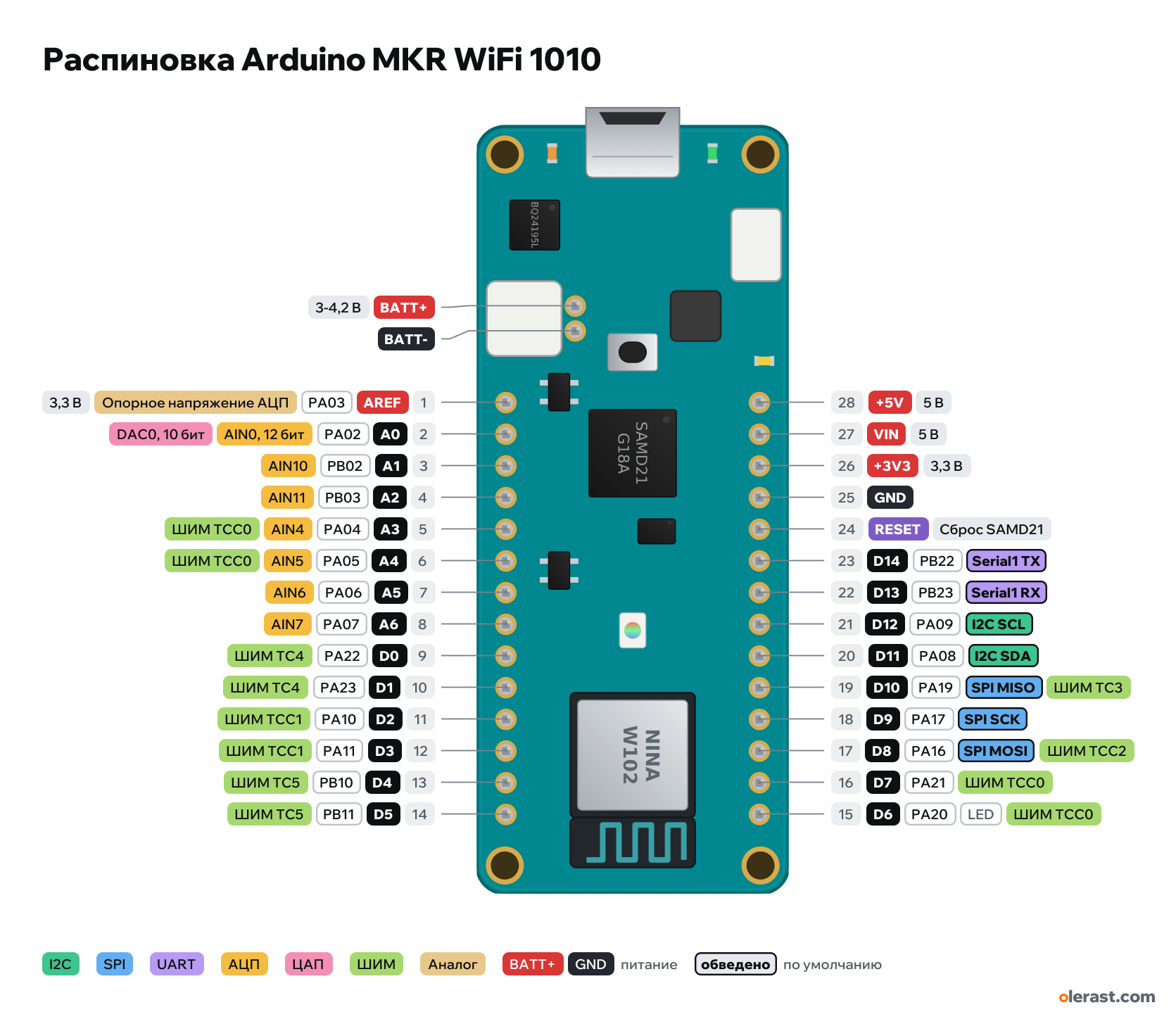
Top view, USB on the left, NINA module on the right, rotated 90° on the diagram.
CompareDownload PNG- Chip
- ATSAMD21G18A, u-blox NINA-W102 (ESP32, Wi-Fi and Bluetooth)
- Logic
- 3.3 V
- Power
- Micro-USB 4.75-5.25 VVINLi-Po 1S battery (JST PH) 3-4.2 V
- Defaults in ArduinoCore-samd (mkrwifi1010)
- I2C: SDA 11, SCL 12SPI: MOSI 8, MISO 10, SCK 9, SS 4UART: TX 14, RX 13LED: 6
Which Arduino MKR WiFi 1010 pins are safe to use
Free to use
D0-D5, D7-D14, A0-A6
Use with care
- D6: onboard LED.
Important
- 3.3 V logic, pins are not 5 V tolerant (datasheet: NOT 5V tolerant). Current per pin up to 7 mA.
- Per the datasheet the +5V pin does not output voltage: it is the 5 V of the USB connector. Without USB you cannot power 5 V modules from it.
- Li-Po 1S 3.7 V battery from 1024 mAh, 2-pin JST PH connector. The BQ24195L charger charges at 512 mA or more: do not connect a smaller battery.
- The battery voltage is read through a divider on PB09 (ADC_BATTERY in the core).
- Wi-Fi and Bluetooth: the NINA-W102 module on the SAMD21 SPI and UART, libraries WiFiNINA and ArduinoBLE.
- I2C (D11 SDA, D12 SCL) is shared with the ECC508 crypto chip and the BQ24195L charger.
- 5-pin connector J4 (JST SH, 1 mm pitch): +5V, WK (D7), SCL, SDA, GND. Not drawn as pins, the nets are the same as on the header.
- The Arduino board file has no pin labels on the top silkscreen: the labels are taken from the ABX00023 pinout.
- The BQ24195L charger powers the board from USB, VIN or the battery and charges the battery. Then two AP2112K-3.3 regulators: one for the SAMD21 and the +3V3 pin, the other for the NINA-W102.
All pins
| Label | Number | Functions | Limits | Check |
|---|---|---|---|---|
| +5V | pin 28 | 5 V | power inputpower output | verifiedPer the datasheet it does not output voltage: connected to the 5 V of the USB connector (through a jumper per the datasheet, through fuse F1 MF-FSMF050 on the schematic). From the battery there is 5 V here only in USB OTG mode.Labelled on other revisions as: 5V |
| VIN | pin 27 | 5 V | power input | verified5 V power input (Arduino specifications), goes to the BQ24195L charger.Labelled on other revisions as: VIN(5V) |
| +3V3 | pin 26 | 3.3 V | power output | verifiedAP2112K-3.3 regulator output (600 mA), it also powers the SAMD21 and the crypto chip.Labelled on other revisions as: VCC |
| GND | pin 25 | Ground | verified | |
| RESET | pin 24 | SAMD21 reset (low = reset) | verifiedDouble-pressing the reset button enters the bootloader if the port disappears.Labelled on other revisions as: RESETN | |
| D14 | PB22, Arduino 14, pin 23 | Serial1 TX (SERCOM5) | not 5 V tolerant | verifiedCurrent per pin up to 7 mA.Labelled on other revisions as: TX |
| D13 | PB23, Arduino 13, pin 22 | Serial1 RX (SERCOM5) | not 5 V tolerant | verifiedCurrent per pin up to 7 mA.Labelled on other revisions as: RX |
| D12 | PA09, Arduino 12, pin 21 | I2C SCL (SERCOM2) | not 5 V tolerant | verifiedBoard I2C bus: the ECC508 crypto chip, the BQ24195L charger and the SCL contact of connector J4 are also on it.Current per pin up to 7 mA.The Arduino specifications list D12 among the PWM pins, but in the mkrwifi1010 core variant PA09 has no PWM assigned.Labelled on other revisions as: SCL |
| D11 | PA08, Arduino 11, pin 20 | NMII2C SDA (SERCOM2) | not 5 V tolerant | verifiedBoard I2C bus: the ECC508 crypto chip, the BQ24195L charger and the SDA contact of connector J4 are also on it.Current per pin up to 7 mA.Labelled on other revisions as: SDA |
| D10 | PA19, Arduino 10, pin 19 | PWM TC3SPI MISO (SERCOM1) | not 5 V tolerant | verifiedCurrent per pin up to 7 mA.Labelled on other revisions as: MISO, CIPO |
| D9 | PA17, Arduino 9, pin 18 | EXTINT1SPI SCK (SERCOM1) | not 5 V tolerant | verifiedCurrent per pin up to 7 mA.Labelled on other revisions as: SCK |
| D8 | PA16, Arduino 8, pin 17 | PWM TCC2EXTINT0SPI MOSI (SERCOM1) | not 5 V tolerant | verifiedCurrent per pin up to 7 mA.Labelled on other revisions as: MOSI, COPI |
| D7 | PA21, Arduino 7, pin 16 | PWM TCC0EXTINT5 | not 5 V tolerant | verifiedThis same pin (PA21) goes to the WK contact of the 5-pin connector J4.Current per pin up to 7 mA. |
| D6 | PA20, Arduino 6, pin 15 | PWM TCC0EXTINT4 | not 5 V tolerantonboard LED | verifiedCurrent per pin up to 7 mA.Yellow LED LED_BUILTIN through a 2N7002 transistor: HIGH = on. |
| AREF | PA03, pin 1 | 3.3 VADC reference voltage (VREFA) | power input | verified |
| A0 | PA02, Arduino A0 (15), pin 2 | AIN0, 12 bitDAC0, 10 bit | not 5 V tolerant | verifiedCurrent per pin up to 7 mA.Labelled on other revisions as: DAC0 |
| A1 | PB02, Arduino A1 (16), pin 3 | AIN10EXTINT2 | not 5 V tolerant | verifiedCurrent per pin up to 7 mA. |
| A2 | PB03, Arduino A2 (17), pin 4 | AIN11EXTINT3 | not 5 V tolerant | verifiedCurrent per pin up to 7 mA. |
| A3 | PA04, Arduino A3 (18), pin 5 | AIN4PWM TCC0 | not 5 V tolerant | verifiedCurrent per pin up to 7 mA. |
| A4 | PA05, Arduino A4 (19), pin 6 | AIN5PWM TCC0 | not 5 V tolerant | verifiedCurrent per pin up to 7 mA. |
| A5 | PA06, Arduino A5 (20), pin 7 | AIN6 | not 5 V tolerant | verifiedCurrent per pin up to 7 mA. |
| A6 | PA07, Arduino A6 (21), pin 8 | AIN7 | not 5 V tolerant | verifiedCurrent per pin up to 7 mA. |
| D0 | PA22, Arduino 0, pin 9 | PWM TC4EXTINT6 | not 5 V tolerant | verifiedCurrent per pin up to 7 mA. |
| D1 | PA23, Arduino 1, pin 10 | PWM TC4EXTINT7 | not 5 V tolerant | verifiedCurrent per pin up to 7 mA. |
| D2 | PA10, Arduino 2, pin 11 | PWM TCC1 | not 5 V tolerant | verifiedCurrent per pin up to 7 mA. |
| D3 | PA11, Arduino 3, pin 12 | PWM TCC1 | not 5 V tolerant | verifiedCurrent per pin up to 7 mA. |
| D4 | PB10, Arduino 4, pin 13 | PWM TC5EXTINT10 | not 5 V tolerant | verifiedCurrent per pin up to 7 mA. |
| D5 | PB11, Arduino 5, pin 14 | PWM TC5EXTINT11 | not 5 V tolerant | verifiedCurrent per pin up to 7 mA. |
| BATT+ | 3.7 V | power inputpower output | verifiedPlus of the Li-Po 1S battery, through fuse F2 (MF-FSMF050) per the schematic.Labelled on other revisions as: + | |
| BATT- | Ground | verifiedLabelled on other revisions as: − |
Sources
Every pin is verified against the manufacturer's documents.
- Arduino MKR WiFi 1010 Datasheet / User Manual (ABX00023)datasheet, checked 20.10.2026table of 28 pins, 3.3 V logic and not 5 V tolerant, the 5V pin is connected to USB, charge current from 512 mA, board 61.50×25.00 mm, holes 2.25 mm, connector positions
- Arduino MKR WiFi 1010 full pinout (ABX00023)manufacturer pinout, checked 20.10.2026rows +5V, VIN, +3V3, GND, RESET, D14-D6 and AREF, A0-A6, D0-D5 with SAMD21 ports, LED_BUILTIN, Li-Po connector, J4 (GND, SDA, SCL, WK, +5V), pin current 7 mA
- Arduino MKR WiFi 1010 schematics (ABX00023)schematic, checked 20.10.2026BQ24195L, two AP2112K-3.3, ECC508, F1 and F2 MF-FSMF050, LED D6 through 2N7002, battery divider on PB09, I2C PA08/PA09 to ECC508 and BQ24195L
- Arduino MKR WiFi 1010 Eagle files (MKRWiFi1010V2.0)board drawing, checked 20.10.2026coordinates of rows J3/J5 (y 2.34 and 22.66 mm, x from 22.135 in 2.54 steps), connectors J4, J7, USB, holes and parts; pin nets
- ArduinoCore-samd: variants/mkrwifi1010 (variant.cpp, variant.h)Arduino core, checked 20.10.2026D0-D14, A0-A6 ↔ SAMD21 ports, PWM (TC/TCC), EXTINT, SPI SERCOM1 on 8/9/10, I2C SERCOM2 on 11/12, Serial1 SERCOM5 on 13/14, LED_BUILTIN 6, ADC_BATTERY on PB09
- Arduino Store: MKR WiFi 1010, Tech Specsuser guide, checked 20.10.2026USB/VIN power 5 V, Li-Po 1S battery 3.7 V from 1024 mAh, pin current 7 mA, PWM 0-8, 10, 12, A3, A4, size 61.5×25 mm
Size: from the Arduino board file MKRWiFi1010V2.0 (Eagle) and the ABX00023 datasheet drawing.
FAQ
- Which Arduino MKR WiFi 1010 pins are I2C, SPI and UART?
- By default in ArduinoCore-samd (mkrwifi1010): I2C: SDA D11, SCL D12; SPI: MOSI D8, MISO D10, SCK D9, SS D4; UART: TX D14, RX D13.
- Which pin is the Arduino MKR WiFi 1010 LED on?
- Yellow LED LED_BUILTIN (D6).
- Are the Arduino MKR WiFi 1010 pins 5 V tolerant?
- No. The logic is 3.3 V and the pins are not 5 V tolerant: use a divider or a level shifter for 5 V signals.
You might also need
Similar boards
Next
Need firmware or a device built on ATSAMD21G18A? I'll build it to order