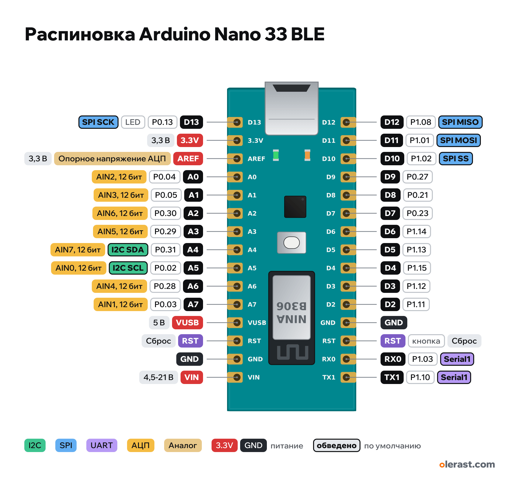
Arduino Nano 33 BLE pinout
Arduino Nano 33 BLE / BLE Sense (nRF52840), nRF52840, 3.3 V logic, 45×18 mm, 30 pins
partly verified17.10.2026
Top view, USB on the left (as on the official pinout), rotated 90° on the diagram.
CompareDownload PNG- Chip
- nRF52840, u-blox NINA-B306
- Logic
- 3.3 V
- Power
- Micro-USB 4.8-5.25 VVIN 4.5-21 V
- Defaults in ArduinoCore-mbed (ARDUINO_NANO33BLE)
- I2C: SDA 18, SCL 19SPI: MOSI 11, MISO 12, SCK 13, SS 10UART: TX 1, RX 0LED: 13
Which Arduino Nano 33 BLE pins are safe to use
Free to use
D0-D12, A0-A7
Use with care
- D13: onboard LED.
Important
- 3.3 V logic, don't apply 5 V to the pins (datasheet: NOT 5V tolerant).
- The "5V" pin here is VUSB and is not connected by default.
- PWM on any digital pin (up to 4 modules with 4 channels each), interrupts on any pin.
- Board sensors (IMU, on the Sense also APDS9960, LPS22HB, HTS221/HS3003) are on a separate internal I2C bus (Wire1), A4/A5 are free.
- Pin current is low (2 mA, 10 mA in high-drive mode): connect an LED only through a resistor of 330 Ω or more.
- Pin rows follow 2.54 mm pitch and 0.6 in width; small components are drawn approximately.
Revisions and clones
- Nano 33 BLE Sense Rev2: different sensors (BMI270 + BMM150, HS3003), same pins.
- Nano 33 BLE Rev2: BMI270 + BMM150 IMU instead of the LSM9DS1.
All pins
| Label | Number | Functions | Limits | Check |
|---|---|---|---|---|
| D12 | P1.08, Arduino 12 | interruptPWM (any pin, up to 16 channels)SPI MISO | not 5 V tolerant | verifiedOutput: standard current 2 mA, in high-drive mode up to 10 mA per pin (nRF52840 datasheet). |
| D11 | P1.01, Arduino 11 | interruptPWM (any pin, up to 16 channels)SPI MOSI | not 5 V tolerant | verifiedOutput: standard current 2 mA, in high-drive mode up to 10 mA per pin (nRF52840 datasheet). |
| D10 | P1.02, Arduino 10 | interruptPWM (any pin, up to 16 channels)SPI SS | not 5 V tolerant | verifiedOutput: standard current 2 mA, in high-drive mode up to 10 mA per pin (nRF52840 datasheet). |
| D9 | P0.27, Arduino 9 | interruptPWM (any pin, up to 16 channels) | not 5 V tolerant | verifiedOutput: standard current 2 mA, in high-drive mode up to 10 mA per pin (nRF52840 datasheet). |
| D8 | P0.21, Arduino 8 | interruptPWM (any pin, up to 16 channels) | not 5 V tolerant | verifiedOutput: standard current 2 mA, in high-drive mode up to 10 mA per pin (nRF52840 datasheet). |
| D7 | P0.23, Arduino 7 | interruptPWM (any pin, up to 16 channels) | not 5 V tolerant | verifiedOutput: standard current 2 mA, in high-drive mode up to 10 mA per pin (nRF52840 datasheet). |
| D6 | P1.14, Arduino 6 | interruptPWM (any pin, up to 16 channels) | not 5 V tolerant | verifiedOutput: standard current 2 mA, in high-drive mode up to 10 mA per pin (nRF52840 datasheet). |
| D5 | P1.13, Arduino 5 | interruptPWM (any pin, up to 16 channels) | not 5 V tolerant | verifiedOutput: standard current 2 mA, in high-drive mode up to 10 mA per pin (nRF52840 datasheet). |
| D4 | P1.15, Arduino 4 | interruptPWM (any pin, up to 16 channels) | not 5 V tolerant | verifiedOutput: standard current 2 mA, in high-drive mode up to 10 mA per pin (nRF52840 datasheet). |
| D3 | P1.12, Arduino 3 | interruptPWM (any pin, up to 16 channels) | not 5 V tolerant | verifiedOutput: standard current 2 mA, in high-drive mode up to 10 mA per pin (nRF52840 datasheet). |
| D2 | P1.11, Arduino 2 | interruptPWM (any pin, up to 16 channels) | not 5 V tolerant | verifiedOutput: standard current 2 mA, in high-drive mode up to 10 mA per pin (nRF52840 datasheet). |
| GND | Ground | verified | ||
| RST | Reset (low = reset) | onboard button | verified | |
| RX0 | P1.03, Arduino 0 | interruptPWM (any pin, up to 16 channels)Serial1 | not 5 V tolerant | not from manufacturerWhich of P1.03 and P1.10 is RX and which is TX: in variant.cpp D0 has the comment "TX", in the datasheet pin table D0 = RX0. The Arduino number and the silkscreen label are correct, the port and role are not verified.Output: standard current 2 mA, in high-drive mode up to 10 mA per pin (nRF52840 datasheet). |
| TX1 | P1.10, Arduino 1 | interruptPWM (any pin, up to 16 channels)Serial1 | not 5 V tolerant | not from manufacturerWhich of P1.03 and P1.10 is RX and which is TX: in variant.cpp D0 has the comment "TX", in the datasheet pin table D0 = RX0. The Arduino number and the silkscreen label are correct, the port and role are not verified.Output: standard current 2 mA, in high-drive mode up to 10 mA per pin (nRF52840 datasheet). |
| D13 | P0.13, Arduino 13 | interruptPWM (any pin, up to 16 channels)SPI SCK | not 5 V tolerantonboard LED | verifiedOutput: standard current 2 mA, in high-drive mode up to 10 mA per pin (nRF52840 datasheet).L LED on the board. LED_BUILTIN = 13. The board also has an RGB LED (LEDR, LEDG, LEDB, light at LOW) on internal pins. |
| 3.3V | 3.3 V | power output | verifiedOutput of the 3.3 V MPM3610 DC-DC converter. | |
| AREF | 3.3 VADC reference voltage | power input | verified | |
| A0 | P0.04, Arduino A0 (14) | interruptPWM (any pin, up to 16 channels)AIN2, 12 bit | not 5 V tolerant | verifiedOutput: standard current 2 mA, in high-drive mode up to 10 mA per pin (nRF52840 datasheet). |
| A1 | P0.05, Arduino A1 (15) | interruptPWM (any pin, up to 16 channels)AIN3, 12 bit | not 5 V tolerant | verifiedOutput: standard current 2 mA, in high-drive mode up to 10 mA per pin (nRF52840 datasheet). |
| A2 | P0.30, Arduino A2 (16) | interruptPWM (any pin, up to 16 channels)AIN6, 12 bit | not 5 V tolerant | verifiedOutput: standard current 2 mA, in high-drive mode up to 10 mA per pin (nRF52840 datasheet). |
| A3 | P0.29, Arduino A3 (17) | interruptPWM (any pin, up to 16 channels)AIN5, 12 bit | not 5 V tolerant | verifiedOutput: standard current 2 mA, in high-drive mode up to 10 mA per pin (nRF52840 datasheet). |
| A4 | P0.31, Arduino A4 (18) | interruptPWM (any pin, up to 16 channels)AIN7, 12 bitI2C SDA (Wire) | not 5 V tolerant | verifiedOutput: standard current 2 mA, in high-drive mode up to 10 mA per pin (nRF52840 datasheet). |
| A5 | P0.02, Arduino A5 (19) | interruptPWM (any pin, up to 16 channels)AIN0, 12 bitI2C SCL (Wire) | not 5 V tolerant | verifiedOutput: standard current 2 mA, in high-drive mode up to 10 mA per pin (nRF52840 datasheet). |
| A6 | P0.28, Arduino A6 (20) | interruptPWM (any pin, up to 16 channels)AIN4, 12 bit | not 5 V tolerant | verifiedOutput: standard current 2 mA, in high-drive mode up to 10 mA per pin (nRF52840 datasheet). |
| A7 | P0.03, Arduino A7 (21) | interruptPWM (any pin, up to 16 channels)AIN1, 12 bit | not 5 V tolerant | verifiedOutput: standard current 2 mA, in high-drive mode up to 10 mA per pin (nRF52840 datasheet). |
| VUSB | 5 V | power inputpower output | verifiedUsually not connected: it joins the 5 V of the USB connector if you solder the VUSB jumper on the back. | |
| RST | Reset (low = reset) | verified | ||
| GND | Ground | verified | ||
| VIN | 5 V | power input | verifiedMPM3610 DC-DC input: 4.5–21 V. |
Sources
Not verified against the manufacturer: 2 of 30 pins. The pin card says what confirms each one and where sources disagree.
- Arduino Nano 33 BLE Datasheet (ABX00030) and BLE Sense (ABX00031)datasheet, checked 17.10.2026table of 30 pins, VUSB is usually not connected, 3.3 V logic and not 5 V tolerant, MPM3610, NINA-B306
- ArduinoCore-mbed: variants/ARDUINO_NANO33BLE/variant.cppArduino core, checked 17.10.2026D0–D13, A0–A7 ↔ nRF52840 pins (P0.xx, P1.xx), SDA A4, SCL A5, SPI 11/12/13
Size: 45×18 mm per the datasheet; rows 15.24 mm apart at 2.54 mm pitch, position along the board is centered.
FAQ
- Which Arduino Nano 33 BLE pins are I2C, SPI and UART?
- By default in ArduinoCore-mbed (ARDUINO_NANO33BLE): I2C: SDA A4, SCL A5; SPI: MOSI D11, MISO D12, SCK D13, SS D10; UART: TX D1, RX D0.
- Which pin is the Arduino Nano 33 BLE LED on?
- D13.
- Are the Arduino Nano 33 BLE pins 5 V tolerant?
- No. The logic is 3.3 V and the pins are not 5 V tolerant: use a divider or a level shifter for 5 V signals.
You might also need
Similar boards
Next
Need firmware or a device built on nRF52? I'll build it to order