Arduino Nano ESP32 pinout
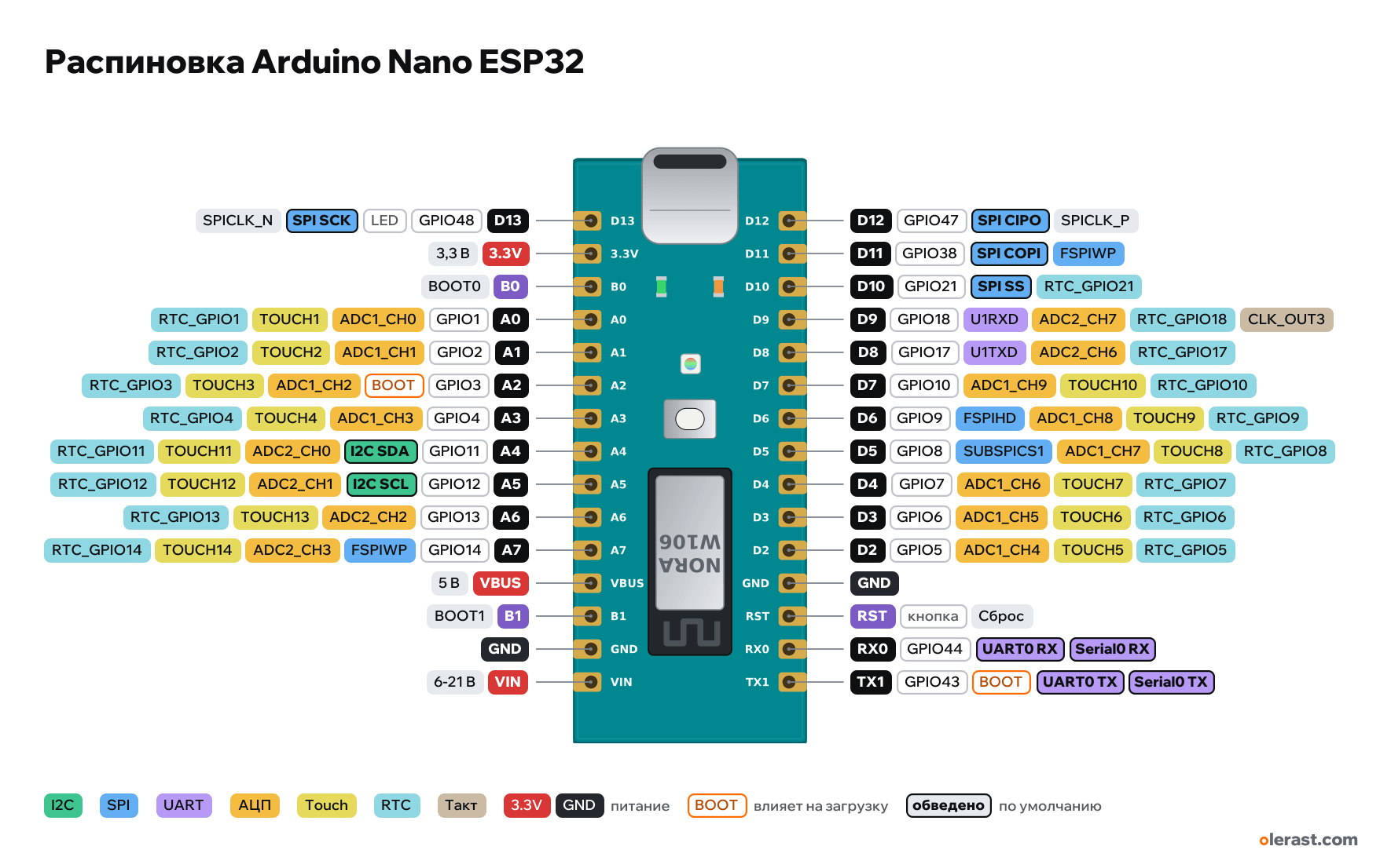
Arduino Nano ESP32 (ESP32-S3), ESP32-S3, 3.3 V logic, 45×18 mm, 30 pins
verified17.10.2026
- D13GPIO48D13 (GPIO48)LEDSPI SCKSPICLK_N
- 3.3V3.3 V
- B0BOOT0
- A0GPIO1A0 (GPIO1)ADC1_CH0TOUCH1RTC_GPIO1
- A1GPIO2A1 (GPIO2)ADC1_CH1TOUCH2RTC_GPIO2
- A2GPIO3A2 (GPIO3)BOOTADC1_CH2TOUCH3RTC_GPIO3
- A3GPIO4A3 (GPIO4)ADC1_CH3TOUCH4RTC_GPIO4
- A4GPIO11A4 (GPIO11)I2C SDAADC2_CH0TOUCH11RTC_GPIO11
- A5GPIO12A5 (GPIO12)I2C SCLADC2_CH1TOUCH12RTC_GPIO12
- A6GPIO13A6 (GPIO13)ADC2_CH2TOUCH13RTC_GPIO13
- A7GPIO14A7 (GPIO14)FSPIWPADC2_CH3TOUCH14RTC_GPIO14
- VBUS5 V
- B1BOOT1
- GND
- VIN6-21 V
- D12GPIO47D12 (GPIO47)SPI CIPOSPICLK_P
- D11GPIO38D11 (GPIO38)SPI COPIFSPIWP
- D10GPIO21D10 (GPIO21)SPI SSRTC_GPIO21
- D9GPIO18D9 (GPIO18)U1RXDADC2_CH7RTC_GPIO18CLK_OUT3
- D8GPIO17D8 (GPIO17)U1TXDADC2_CH6RTC_GPIO17
- D7GPIO10D7 (GPIO10)ADC1_CH9TOUCH10RTC_GPIO10
- D6GPIO9D6 (GPIO9)FSPIHDADC1_CH8TOUCH9RTC_GPIO9
- D5GPIO8D5 (GPIO8)SUBSPICS1ADC1_CH7TOUCH8RTC_GPIO8
- D4GPIO7D4 (GPIO7)ADC1_CH6TOUCH7RTC_GPIO7
- D3GPIO6D3 (GPIO6)ADC1_CH5TOUCH6RTC_GPIO6
- D2GPIO5D2 (GPIO5)ADC1_CH4TOUCH5RTC_GPIO5
- GND
- RSTbuttonReset
- RX0GPIO44D0 (GPIO44)UART0 RXSerial0 RX
- TX1GPIO43D1 (GPIO43)BOOTUART0 TXSerial0 TX
Top view, USB on the left (as on the official pinout), rotated 90° on the diagram.
CompareDownload PNG- Chip
- ESP32-S3, u-blox NORA-W106-10B (ESP32-S3, 8 MB PSRAM) + 16 MB flash
- Logic
- 3.3 V
- Power
- USB-C 4.75-5.25 VVIN 6-21 V
- Defaults in arduino-esp32 (Arduino Nano ESP32, Arduino numbering)
- I2C: SDA 11, SCL 12SPI: MOSI 38, MISO 47, SCK 48, SS 21UART: TX 43, RX 44LED: 48
Which Arduino Nano ESP32 pins are safe to use
Free to use
GPIO1, GPIO2, GPIO4-14, GPIO17, GPIO18, GPIO21, GPIO38, GPIO44, GPIO47
Use with care
- GPIO3: strapping: the level at power-up selects the boot mode.
- GPIO43: signal at boot.
- GPIO48: onboard LED.
Important
- 3.3 V logic, don't apply 5 V to the pins.
- In the Arduino IDE the default is "By Arduino pin" numbering (D2 = 2), while GPIO-based libraries use "By GPIO number" (Tools → Pin Numbering). This mix-up is the main reason for "it doesn't work".
- GPIO0 (green RGB channel) and GPIO46 (red) are strapping pins: not brought out to the header.
- ADC: A0-A7 (A0-A3 are ADC1, A4-A7 are ADC2, which may not work with Wi-Fi).
- Programming goes through the built-in ESP32-S3 USB; if the port disappears, double-press RST (DFU bootloader).
- Where the Nano has AREF and a second RST, the Nano ESP32 has the service pins B0 and B1 (boot mode selection).
- Pin rows follow 2.54 mm pitch and 0.6 in width; small components are drawn approximately.
All pins
| Label | Number | Functions | Limits | Check |
|---|---|---|---|---|
| D12 | GPIO47, Arduino D12 (GPIO47) | interruptPWM (LEDC)SPICLK_PSPI CIPO (MISO) | not 5 V tolerant | verified |
| D11 | GPIO38, Arduino D11 (GPIO38) | interruptPWM (LEDC)FSPIWPSPI COPI (MOSI) | not 5 V tolerant | verified |
| D10 | GPIO21, Arduino D10 (GPIO21) | interruptPWM (LEDC)RTC_GPIO21SPI SS | not 5 V tolerant | verified |
| D9 | GPIO18, Arduino D9 (GPIO18) | interruptPWM (LEDC)ADC2_CH7RTC_GPIO18U1RXDCLK_OUT3 | not 5 V tolerantADC2 doesn't work with Wi-Fi on | verifiedADC2: with Wi-Fi on, reading may not work (arbitration with Wi-Fi). Use GPIO1–10 for ADC. |
| D8 | GPIO17, Arduino D8 (GPIO17) | interruptPWM (LEDC)ADC2_CH6RTC_GPIO17U1TXD | not 5 V tolerantADC2 doesn't work with Wi-Fi on | verifiedADC2: with Wi-Fi on, reading may not work (arbitration with Wi-Fi). Use GPIO1–10 for ADC. |
| D7 | GPIO10, Arduino D7 (GPIO10) | interruptPWM (LEDC)ADC1_CH9TOUCH10RTC_GPIO10 | not 5 V tolerant | verified |
| D6 | GPIO9, Arduino D6 (GPIO9) | interruptPWM (LEDC)ADC1_CH8TOUCH9RTC_GPIO9FSPIHD | not 5 V tolerant | verified |
| D5 | GPIO8, Arduino D5 (GPIO8) | interruptPWM (LEDC)ADC1_CH7TOUCH8RTC_GPIO8SUBSPICS1 | not 5 V tolerant | verified |
| D4 | GPIO7, Arduino D4 (GPIO7) | interruptPWM (LEDC)ADC1_CH6TOUCH7RTC_GPIO7 | not 5 V tolerant | verified |
| D3 | GPIO6, Arduino D3 (GPIO6) | interruptPWM (LEDC)ADC1_CH5TOUCH6RTC_GPIO6 | not 5 V tolerant | verified |
| D2 | GPIO5, Arduino D2 (GPIO5) | interruptPWM (LEDC)ADC1_CH4TOUCH5RTC_GPIO5 | not 5 V tolerant | verified |
| GND | Ground | verified | ||
| RST | Reset (low = reset) | onboard button | verified | |
| RX0 | GPIO44, Arduino D0 (GPIO44) | interruptPWM (LEDC)UART0 RXSerial0 RX | not 5 V tolerant | verified |
| TX1 | GPIO43, Arduino D1 (GPIO43) | interruptPWM (LEDC)UART0 TXSerial0 TX | not 5 V tolerantoutputs a signal at boot | verified |
| D13 | GPIO48, Arduino D13 (GPIO48) | interruptPWM (LEDC)SPICLK_NSPI SCK | not 5 V tolerantonboard LED | verifiedL LED on the board (GPIO48). LED_BUILTIN = D13. RGB LED: R = GPIO46, G = GPIO0, B = GPIO45 (lit when LOW). |
| 3.3V | 3.3 V | power output | verifiedMP2322 DC-DC 3.3 V output. | |
| B0 | BOOT0: boot mode | verifiedService pin for boot mode selection ("Board Reset 0" in the datasheet). Leave unconnected for normal use. | ||
| A0 | GPIO1, Arduino A0 (GPIO1) | interruptPWM (LEDC)ADC1_CH0TOUCH1RTC_GPIO1 | not 5 V tolerant | verified |
| A1 | GPIO2, Arduino A1 (GPIO2) | interruptPWM (LEDC)ADC1_CH1TOUCH2RTC_GPIO2 | not 5 V tolerant | verified |
| A2 | GPIO3, Arduino A2 (GPIO3) | interruptPWM (LEDC)ADC1_CH2TOUCH3RTC_GPIO3 | not 5 V tolerantaffects boot (strapping) | verifiedStrapping: JTAG signal source selection. Floating by default, no effect unless the eFuse was changed. |
| A3 | GPIO4, Arduino A3 (GPIO4) | interruptPWM (LEDC)ADC1_CH3TOUCH4RTC_GPIO4 | not 5 V tolerant | verified |
| A4 | GPIO11, Arduino A4 (GPIO11) | interruptPWM (LEDC)ADC2_CH0TOUCH11RTC_GPIO11I2C SDA | not 5 V tolerantADC2 doesn't work with Wi-Fi on | verifiedADC2: with Wi-Fi on, reading may not work (arbitration with Wi-Fi). Use GPIO1–10 for ADC. |
| A5 | GPIO12, Arduino A5 (GPIO12) | interruptPWM (LEDC)ADC2_CH1TOUCH12RTC_GPIO12I2C SCL | not 5 V tolerantADC2 doesn't work with Wi-Fi on | verifiedADC2: with Wi-Fi on, reading may not work (arbitration with Wi-Fi). Use GPIO1–10 for ADC. |
| A6 | GPIO13, Arduino A6 (GPIO13) | interruptPWM (LEDC)ADC2_CH2TOUCH13RTC_GPIO13 | not 5 V tolerantADC2 doesn't work with Wi-Fi on | verifiedADC2: with Wi-Fi on, reading may not work (arbitration with Wi-Fi). Use GPIO1–10 for ADC. |
| A7 | GPIO14, Arduino A7 (GPIO14) | interruptPWM (LEDC)ADC2_CH3TOUCH14RTC_GPIO14FSPIWP | not 5 V tolerantADC2 doesn't work with Wi-Fi on | verifiedADC2: with Wi-Fi on, reading may not work (arbitration with Wi-Fi). Use GPIO1–10 for ADC. |
| VBUS | 5 V | power output | verified5 V from USB-C. When powered from VIN there is nothing here. | |
| B1 | BOOT1: boot mode | verifiedService pin for boot mode selection ("Board Reset 1" in the datasheet). Leave unconnected for normal use. | ||
| GND | Ground | verified | ||
| VIN | 9 V | power input | verifiedMP2322 DC-DC input: 6-21 V. |
Sources
Every pin is verified against the manufacturer's documents.
- Arduino Nano ESP32 Datasheet (ABX00083)datasheet, checked 17.10.2026pin table, VBUS, 3.3 V from the MP2322, VIN 6-21 V, pin current up to 40 mA output / 28 mA input, 3.3 V logic
- arduino-esp32: variants/arduino_nano_nora/pins_arduino.hArduino core, checked 17.10.2026D0 = 44, D1 = 43, D2–D7 = 5–10, D8 = 17, D9 = 18, D10 = 21, D11 = 38, D12 = 47, D13 = 48, A0–A3 = 1–4, A4 = 11, A5 = 12, A6 = 13, A7 = 14; RGB 46/0/45; SDA A4, SCL A5
- ESP32-S3 Series Datasheet (Espressif)datasheet, checked 15.10.2026pin functions: ADC1_CH0–9 on GPIO1–10, ADC2_CH0–9 on GPIO11–20, TOUCH1–14, RTC GPIO0–21, USB GPIO19/20, JTAG GPIO39–42, UART0 GPIO43/44, strapping GPIO0/3/45/46
- ESP-IDF: GPIO (ESP32-S3)user guide, checked 15.10.2026GPIO26–32 are used by SPI flash/PSRAM, GPIO33–37 are used on modules with Octal flash/PSRAM, strapping pins, USB
- arduino-esp32: variants/esp32s3/pins_arduino.hArduino core, checked 15.10.2026defaults: TX 43, RX 44, SDA 8, SCL 9, SS 10, MOSI 11, MISO 13, SCK 12
Size: 45×18 mm per the datasheet; rows 15.24 mm apart at 2.54 mm pitch, position along the board is centered.
FAQ
- Which Arduino Nano ESP32 pins are I2C, SPI and UART?
- By default in arduino-esp32 (Arduino Nano ESP32, Arduino numbering): I2C: SDA GPIO11, SCL GPIO12; SPI: MOSI GPIO38, MISO GPIO47, SCK GPIO48, SS GPIO21; UART: TX GPIO43, RX GPIO44.
- Which pin is the Arduino Nano ESP32 LED on?
- GPIO48.
- Are the Arduino Nano ESP32 pins 5 V tolerant?
- No. The logic is 3.3 V and the pins are not 5 V tolerant: use a divider or a level shifter for 5 V signals.
- Does ADC2 on the Arduino Nano ESP32 work with Wi-Fi on?
- No. ADC2 pins (GPIO11-14, GPIO17, GPIO18) can't read analog while Wi-Fi is on. With Wi-Fi, use GPIO1-10 for the ADC.
You might also need
Similar boards
Next
- Emotion keychainmy ESP32-S3 project, prototype
- Troll Botmy ESP32-S3 project, prototype
- olerast PULSEmy ESP32-S3 project, in development
Need firmware or a device built on ESP32? I'll build it to order