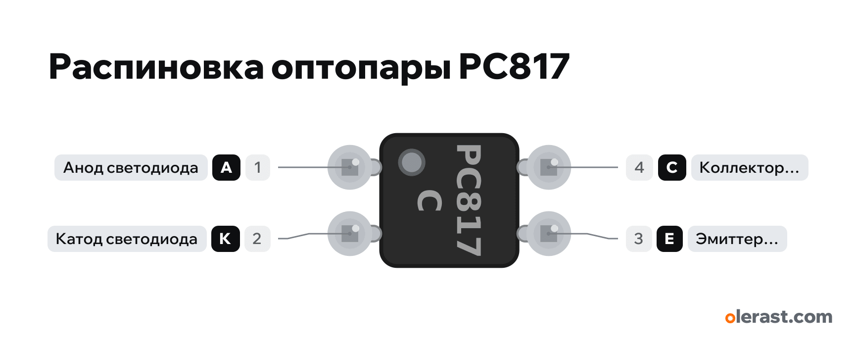
PC817 optocoupler pinout
PC817 optocoupler (DIP-4), PC817, 5 V logic, 5.62×9.7 mm, 4 pins
verified20.10.2026
Top view, dot at pin 1 bottom left: 1 anode and 2 cathode at the bottom, 3 emitter and 4 collector at the top (4 above 1), rotated 90° on the diagram.
Download PNG- Chip
- PC817
- Logic
- 5 V
Important
- Input: LED (1 anode, 2 cathode), forward drop 1.2 V. Current 5-20 mA through a resistor: R = (Vsupply - 1.2) / I. Without a resistor the LED will burn out, the builder flags an error.
- Output: phototransistor (4 collector, 3 emitter). For a signal to a GPIO: emitter to the Ground of the second circuit, collector to the GPIO with a pull-up to its supply (INPUT_PULLUP or 4.7-10 kΩ). LED on: GPIO reads LOW.
- Current transfer ratio CTR 50-600% at 5 mA: with a 5 mA input the output reliably sinks from 2.5 mA. The letter after PC817 (A, B, C, D) sets the CTR range.
- The optocoupler is slow: turn-on and turn-off take about 4-18 µs. It is not suitable for PWM above a few kHz or for I2C.
- Do not connect the Grounds of the two sides: that is the point of isolation (relay module, 220 V input through a resistor and diode, galvanic isolation of a sensor).
- The input LED is driven from a GPIO through a resistor: at 3.3 V and 5 mA about 390 Ω, at 5 V and 10 mA about 390 Ω.
Revisions and clones
- PC817 in SMD (PC817XxNIP1B, "C817" on the package): same pin order.
- PC847 and similar: four optocouplers in DIP-16, different pin order.
- Equivalents EL817 (Everlight), LTV-817 (Lite-On), KP1010: same pin order, CTR and speed per their datasheets.
All pins
| Label | Number | Functions | Limits | Check |
|---|---|---|---|---|
| A | pin 1 | LED anode: from a GPIO through a resistor | verifiedLabelled on other revisions as: Anode, 1 | |
| K | pin 2 | LED cathode: to GND | verifiedLabelled on other revisions as: Cathode, 2 | |
| E | pin 3 | Phototransistor emitter: to the Ground of the second circuit | verifiedLabelled on other revisions as: Emitter, 3 | |
| C | pin 4 | Phototransistor collector: to the input through a pull-up | verifiedLabelled on other revisions as: Collector, 4 |
Sources
Every pin is verified against the manufacturer's documents.
- Sharp PC817XxNSZ1B Series (OP18002EN, 15.01.2018)datasheet, checked 20.10.2026DIP-4: 1 Anode, 2 Cathode, 3 Emitter, 4 Collector; IF up to 50 mA, VR 6 V; VF 1.2 V typ., 1.4 V max at 20 mA; VCEO 80 V, IC 50 mA, PC 150 mW; CTR 50-600% at IF 5 mA and VCE 5 V; isolation 5 kV
Size: DIP-4 package 4.6×6.5 mm, 2.54 pitch, rows 7.62 apart (approximate).