MAX98357A pinout
MAX98357A, 3 W I2S amplifier (Adafruit 3006), Maxim MAX98357A, 3.3 V logic, 17.78×19.05 mm, 9 pins
verified17.10.2026
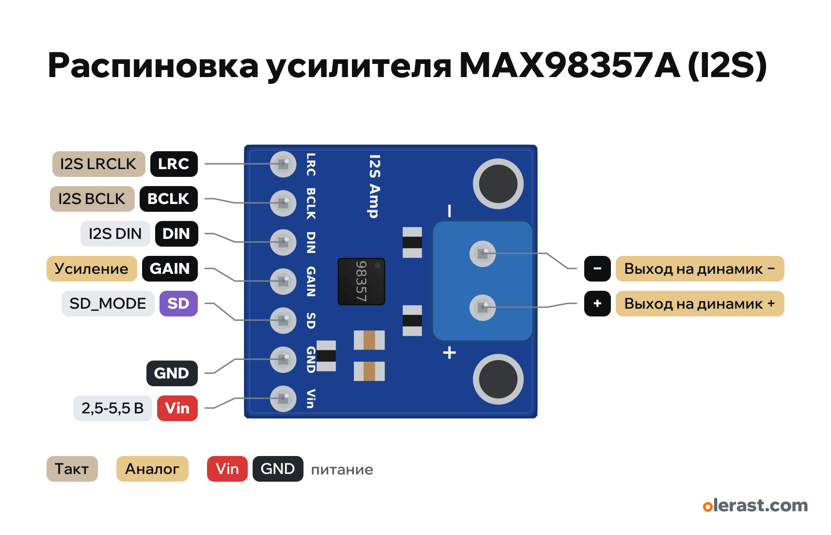
Top view, pin row at the bottom, speaker terminal block at the top, rotated 90° on the diagram.
BuyDownload PNG- Chip
- Maxim MAX98357A
- Logic
- 3.3 V
- Power
- Vin 2.5-5.5 V
Important
- I2S: BCLK, LRC and DIN to any GPIOs that the core can route to I2S (on the ESP32 any outputs). MCLK is not needed.
- The current at full volume into 4 Ω is up to 650 mA from 5 V: from the 5V pin of a board on USB, dips and resets are possible.
- Default gain 9 dB, output (L+R)/2 at 5 V supply (at another supply choose the SD resistor).
- For loudness power it from 5 V; the I2S logic can still be 3.3 V.
- The output is bridged: do not connect either the "+" or the "−" of the speaker to ground.
Revisions and clones
- Clones with the same layout are sold as MAX98357A I2S; some have no resistor on SD, in that case pull SD to Vin yourself.
- Adafruit has revision B (stereo variant of the layout), this describes the original Breakout.brd file.
All pins
| Label | Number | Functions | Limits | Check |
|---|---|---|---|---|
| LRC | I2S LRCLK (WS): left or right channel | 5 V tolerant | verifiedLogic 3.3–5 V. | |
| BCLK | I2S BCLK: bit clock | 5 V tolerant | verified | |
| DIN | I2S DIN: data of both channels | 5 V tolerant | verified | |
| GAIN | Gain: 3, 6, 9, 12 or 15 dB | verifiedNot connected: 9 dB. To GND: 12 dB. Through 100 kΩ to GND: 15 dB. To Vin: 6 dB. Through 100 kΩ to Vin: 3 dB.After changing the gain a power cycle may be needed. | ||
| SD | SD_MODE: shutdown and channel select | onboard pull-up | verifiedThe board has 1 MΩ to Vin: at 5 V the output is (L+R)/2. The chip has a 100 kΩ pull-down to ground.Below 0.16 V: shut down (0.6 µA). 0.16–0.77 V: (L+R)/2. 0.77–1.4 V: right. Above 1.4 V: left.Can be driven from a GPIO: a low level shuts the amplifier down. | |
| GND | Ground | verified | ||
| Vin | 5 V | power input | verified | |
| − | Speaker output − (BTL bridge, 330 kHz PWM) | verifiedDo not connect to ground: the output is bridged.Labelled on other revisions as: -, VO- | ||
| + | Speaker output + (BTL bridge, 330 kHz PWM) | verifiedSpeaker 4–8 Ω. Do not connect to the input of another amplifier: the output is PWM and the speaker coil acts as the filter.Labelled on other revisions as: VO+ |
Sources
Every pin is verified against the manufacturer's documents.
- Adafruit: Adafruit MAX98357 Breakout.brd (Eagle)board drawing, checked 17.10.2026outline 17.78×19.05, 7-pin row (Vin, GND, SD, GAIN, DIN, BCLK, LRC from right to left) at y 16.51, 3.5 mm terminal block (VO−, VO+), holes, R1 1 MΩ
- Adafruit Learn: MAX98357 I2S Class-D Mono Amp, Pinoutsuser guide, checked 17.10.2026power 2.5–5.5 V, logic 3.3–5 V, GAIN table, SD_MODE thresholds, 1 MΩ on SD, speaker from 4 Ω, bridged output
- Adafruit: I2S 3W Class D Amplifier Breakout - MAX98357A (3006)user guide, checked 17.10.2026size 19.4×17.8×3 mm, terminal block included
- Maxim MAX98357A/MAX98357B datasheet (Adafruit copy)datasheet, checked 17.10.2026power 2.5–5.5 V, 3.2 W into 4 Ω at 5 V, quiescent current 2.4–2.75 mA, shutdown 0.6 µA (SD_MODE = 0 V), MCLK not needed, digital input VIH 1.3 V
Size: from the Eagle outline; on the Adafruit site 19.4×17.8×3 mm.
FAQ
- What supply voltage does the MAX98357A need?
- Vin: 2.5-5.5 V. 3.3 V logic.