Arduino Zero pinout
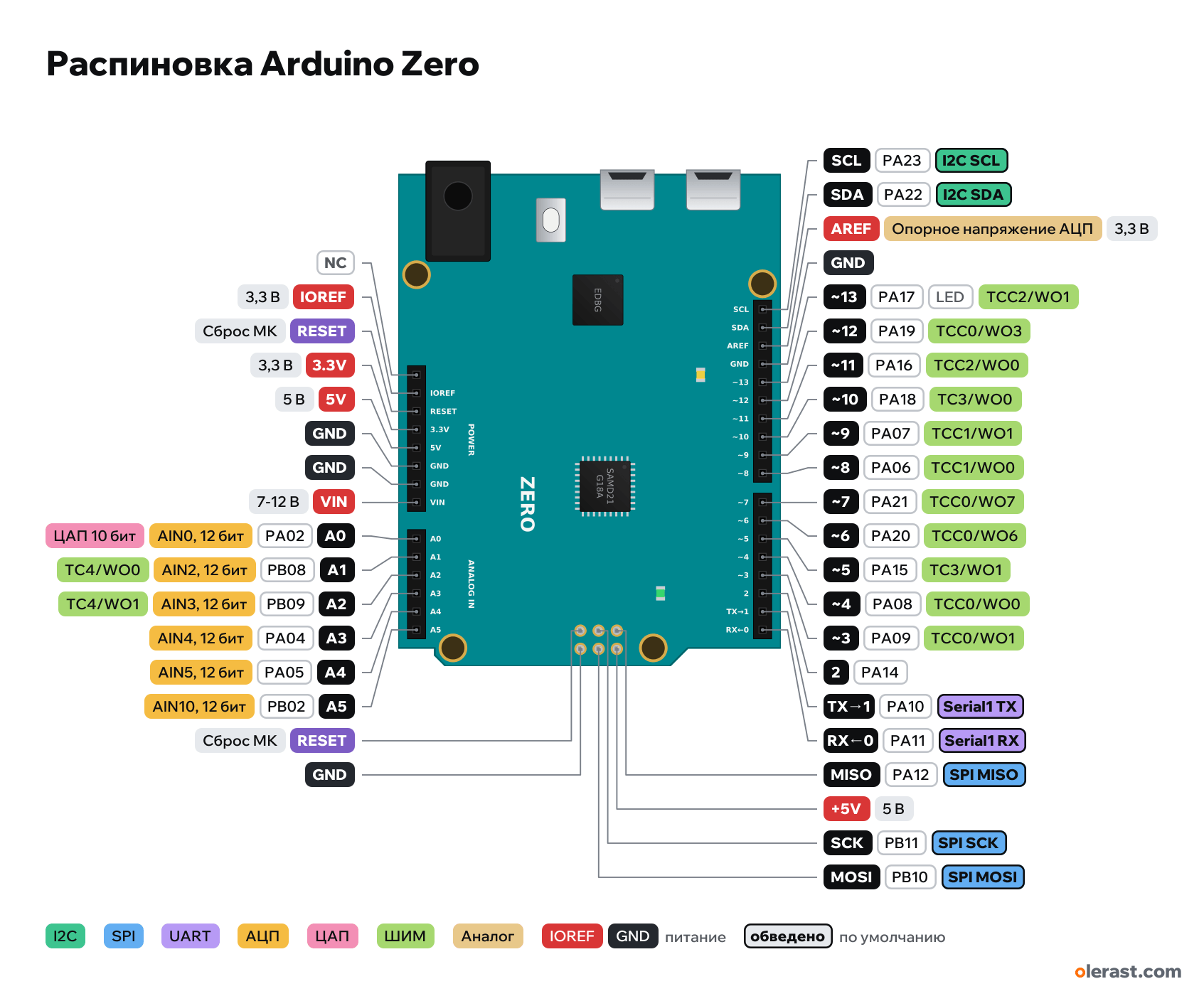
Arduino Zero (ATSAMD21G18), ATSAMD21G18A, 3.3 V logic, 68.58×53.34 mm, 38 pins
verified17.10.2026
- NC
- IOREF3.3 V
- RESETMCU reset
- 3.3V3.3 V
- 5V5 V
- GND
- GND
- VIN7-12 V
- A0PA0214AIN0, 12 bit10-bit DAC
- A1PB0815AIN2, 12 bitPWM TC4/WO0
- A2PB0916AIN3, 12 bitPWM TC4/WO1
- A3PA0417AIN4, 12 bit
- A4PA0518AIN5, 12 bit
- A5PB0219AIN10, 12 bit
- RESETMCU reset
- GND
- SCLPA23I2C SCL
- SDAPA22I2C SDA
- AREFADC reference voltage3.3 V
- GND
- ~13PA1713LEDPWM TCC2/WO1
- ~12PA1912PWM TCC0/WO3
- ~11PA1611PWM TCC2/WO0
- ~10PA1810PWM TC3/WO0
- ~9PA079PWM TCC1/WO1
- ~8PA068PWM TCC1/WO0
- ~7PA217PWM TCC0/WO7
- ~6PA206PWM TCC0/WO6
- ~5PA155PWM TC3/WO1
- ~4PA084PWM TCC0/WO0
- ~3PA093PWM TCC0/WO1
- 2PA14
- TX→1PA101Serial1 TX
- RX←0PA110Serial1 RX
- MISOPA12SPI MISO
- +5V5 V
- SCKPB11SPI SCK
- MOSIPB10SPI MOSI
Top view, two USB ports and the DC jack on the left, rotated 90° on the diagram.
CompareDownload PNG- Chip
- ATSAMD21G18A
- Logic
- 3.3 V
- Power
- Micro-USB "Programming" or "Native" 4.75-5.25 VVIN / DC jack 7-12 V5V
- Defaults in ArduinoCore-samd (Arduino Zero)
- I2C: SDA 20, SCL 21SPI: MOSI 23, MISO 22, SCK 24, SS 10UART: TX 1, RX 0LED: 13
Which Arduino Zero pins are safe to use
Free to use
D0-D12, A0-A5, MISO, MOSI, SCK, SCL, SDA
Use with care
- D13: onboard LED.
Important
- 3.3 V logic, do not apply 5 V to pins: 5 V shields without IOREF will burn the SAMD21.
- Current per pin up to 7 mA.
- SPI is only on ICSP. I2C has its own SDA/SCL next to AREF (not A4/A5).
- Two USB ports: "Programming" (EDBG, Serial) and "Native" (SerialUSB). You can flash through either.
- PWM on 3–13 (D2 has none), A0 is a 10-bit DAC, the ADC is 12-bit.
- I did not check the tilde (~) silkscreen on 3–13 against photos: labels follow the datasheet and the core.
All pins
| Label | Number | Functions | Limits | Check |
|---|---|---|---|---|
| SCL | PA23 | I2C SCL (SERCOM3) | not 5 V tolerant | verifiedUp to 7 mA per pin (strong DRVSTR mode), normally 2–3 mA: drive LEDs through a resistor of 1 kΩ or more.Separate I2C SCL (PA23): not tied to A5 as on the Uno. |
| SDA | PA22 | I2C SDA (SERCOM3) | not 5 V tolerant | verifiedUp to 7 mA per pin (strong DRVSTR mode), normally 2–3 mA: drive LEDs through a resistor of 1 kΩ or more.Separate I2C SDA (PA22): not tied to A4 as on the Uno. |
| AREF | 3.3 VADC reference voltage | power input | verifiedExternal reference for analogRead. No more than 3.3 V. | |
| GND | Ground | verified | ||
| ~13 | PA17, Arduino 13 | PWM TCC2/WO1EXTINT1 | not 5 V tolerantonboard LED | verifiedUp to 7 mA per pin (strong DRVSTR mode), normally 2–3 mA: drive LEDs through a resistor of 1 kΩ or more.L LED on the board. LED_BUILTIN = 13. |
| ~12 | PA19, Arduino 12 | PWM TCC0/WO3EXTINT3 | not 5 V tolerant | verifiedUp to 7 mA per pin (strong DRVSTR mode), normally 2–3 mA: drive LEDs through a resistor of 1 kΩ or more. |
| ~11 | PA16, Arduino 11 | PWM TCC2/WO0EXTINT0 | not 5 V tolerant | verifiedUp to 7 mA per pin (strong DRVSTR mode), normally 2–3 mA: drive LEDs through a resistor of 1 kΩ or more. |
| ~10 | PA18, Arduino 10 | PWM TC3/WO0EXTINT2 | not 5 V tolerant | verifiedUp to 7 mA per pin (strong DRVSTR mode), normally 2–3 mA: drive LEDs through a resistor of 1 kΩ or more. |
| ~9 | PA07, Arduino 9 | PWM TCC1/WO1EXTINT7 | not 5 V tolerant | verifiedUp to 7 mA per pin (strong DRVSTR mode), normally 2–3 mA: drive LEDs through a resistor of 1 kΩ or more. |
| ~8 | PA06, Arduino 8 | PWM TCC1/WO0EXTINT6 | not 5 V tolerant | verifiedUp to 7 mA per pin (strong DRVSTR mode), normally 2–3 mA: drive LEDs through a resistor of 1 kΩ or more. |
| ~7 | PA21, Arduino 7 | PWM TCC0/WO7EXTINT5 | not 5 V tolerant | verifiedUp to 7 mA per pin (strong DRVSTR mode), normally 2–3 mA: drive LEDs through a resistor of 1 kΩ or more. |
| ~6 | PA20, Arduino 6 | PWM TCC0/WO6EXTINT4 | not 5 V tolerant | verifiedUp to 7 mA per pin (strong DRVSTR mode), normally 2–3 mA: drive LEDs through a resistor of 1 kΩ or more. |
| ~5 | PA15, Arduino 5 | PWM TC3/WO1EXTINT15 | not 5 V tolerant | verifiedUp to 7 mA per pin (strong DRVSTR mode), normally 2–3 mA: drive LEDs through a resistor of 1 kΩ or more. |
| ~4 | PA08, Arduino 4 | PWM TCC0/WO0NMI (no attachInterrupt) | not 5 V tolerant | verifiedUp to 7 mA per pin (strong DRVSTR mode), normally 2–3 mA: drive LEDs through a resistor of 1 kΩ or more. |
| ~3 | PA09, Arduino 3 | PWM TCC0/WO1EXTINT9 | not 5 V tolerant | verifiedUp to 7 mA per pin (strong DRVSTR mode), normally 2–3 mA: drive LEDs through a resistor of 1 kΩ or more. |
| 2 | PA14, Arduino 2 | EXTINT14 | not 5 V tolerant | verifiedOn the Zero, D2 and D4 are wired differently than on the M0 Pro: D2 = PA14, D4 = PA08.Up to 7 mA per pin (strong DRVSTR mode), normally 2–3 mA: drive LEDs through a resistor of 1 kΩ or more. |
| TX→1 | PA10, Arduino 1 | Serial1 TX (SERCOM0)EXTINT10 | not 5 V tolerant | verifiedUp to 7 mA per pin (strong DRVSTR mode), normally 2–3 mA: drive LEDs through a resistor of 1 kΩ or more. |
| RX←0 | PA11, Arduino 0 | Serial1 RX (SERCOM0)EXTINT11 | not 5 V tolerant | verifiedUp to 7 mA per pin (strong DRVSTR mode), normally 2–3 mA: drive LEDs through a resistor of 1 kΩ or more. |
| - | not connected | verifiedNot connected (reserved). | ||
| IOREF | 3.3 V | power output | verifiedThe board logic level is 3.3 V: 5 V shields with IOREF switch automatically, others can burn the pins. | |
| RESET | MCU reset (low = reset) | verified | ||
| 3.3V | 3.3 V | power output | verified | |
| 5V | 5 V | power inputpower output | verified | |
| GND | Ground | verified | ||
| GND | Ground | verified | ||
| VIN | 9 V | power input | verified | |
| A0 | PA02, Arduino A0 (14) | AIN0, 12 bit10-bit DAC | not 5 V tolerant | verifiedUp to 7 mA per pin (strong DRVSTR mode), normally 2–3 mA: drive LEDs through a resistor of 1 kΩ or more. |
| A1 | PB08, Arduino A1 (15) | AIN2, 12 bitPWM TC4/WO0 | not 5 V tolerant | verifiedUp to 7 mA per pin (strong DRVSTR mode), normally 2–3 mA: drive LEDs through a resistor of 1 kΩ or more. |
| A2 | PB09, Arduino A2 (16) | AIN3, 12 bitPWM TC4/WO1 | not 5 V tolerant | verifiedUp to 7 mA per pin (strong DRVSTR mode), normally 2–3 mA: drive LEDs through a resistor of 1 kΩ or more. |
| A3 | PA04, Arduino A3 (17) | AIN4, 12 bit | not 5 V tolerant | verifiedUp to 7 mA per pin (strong DRVSTR mode), normally 2–3 mA: drive LEDs through a resistor of 1 kΩ or more. |
| A4 | PA05, Arduino A4 (18) | AIN5, 12 bit | not 5 V tolerant | verifiedUp to 7 mA per pin (strong DRVSTR mode), normally 2–3 mA: drive LEDs through a resistor of 1 kΩ or more. |
| A5 | PB02, Arduino A5 (19) | AIN10, 12 bit | not 5 V tolerant | verifiedUp to 7 mA per pin (strong DRVSTR mode), normally 2–3 mA: drive LEDs through a resistor of 1 kΩ or more. |
| MISO | PA12 | SPI MISO (SERCOM4) | not 5 V tolerant | verifiedUp to 7 mA per pin (strong DRVSTR mode), normally 2–3 mA: drive LEDs through a resistor of 1 kΩ or more. |
| +5V | 5 V | power inputpower output | verified | |
| SCK | PB11 | SPI SCK (SERCOM4) | not 5 V tolerant | verifiedUp to 7 mA per pin (strong DRVSTR mode), normally 2–3 mA: drive LEDs through a resistor of 1 kΩ or more. |
| MOSI | PB10 | SPI MOSI (SERCOM4) | not 5 V tolerant | verifiedUp to 7 mA per pin (strong DRVSTR mode), normally 2–3 mA: drive LEDs through a resistor of 1 kΩ or more. |
| RESET | MCU reset | verified | ||
| GND | Ground | verified |
Sources
Every pin is verified against the manufacturer's documents.
- Arduino Zero (ABX00003) Datasheet and board pagedatasheet, checked 17.10.20263.3 V logic, 7 mA per pin, VIN 7–12 V, two USB ports (Programming via EDBG and Native), SPI only on ICSP, DAC on A0
- ArduinoCore-samd: variants/arduino_zero/variant.cppArduino core, checked 17.10.2026D0–D13, A0–A5, SDA/SCL, MISO/MOSI/SCK ↔ PA/PB ports, PWM (TCC/TC) on 3–13 and A1/A2, EXTINT, DAC on PA02
- Microchip SAM D21/DA1 Family Datasheetdatasheet, checked 17.10.2026pin multiplexing (SERCOM, TC/TCC, AIN), pins are not 5 V tolerant (VDD + 0.3 V)
- Arduino UNO R3: Eagle files UNO-TH_Rev3e (Uno outline and connectors, shared by boards of this size)board drawing, checked 17.10.2026size 68.58×53.34 mm, connector pad centers, ICSP and holes are the same on boards in the Uno form factor
Size: size and connectors as on the Uno R3; components approximate.
FAQ
- Which Arduino Zero pins are I2C, SPI and UART?
- By default in ArduinoCore-samd (Arduino Zero): I2C: SDA D20, SCL D21; SPI: MOSI D23, MISO D22, SCK D24, SS D10; UART: TX D1, RX D0.
- Which pin is the Arduino Zero LED on?
- L LED on D13.
- Are the Arduino Zero pins 5 V tolerant?
- No. The logic is 3.3 V and the pins are not 5 V tolerant: use a divider or a level shifter for 5 V signals.
You might also need
Similar boards
Next
Need firmware or a device built on ATSAMD21G18A? I'll build it to order