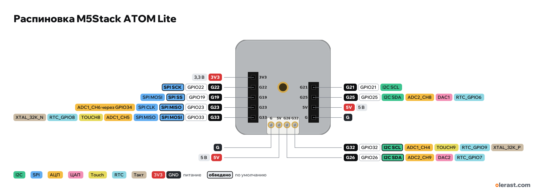
M5Stack ATOM Lite pinout
M5Stack ATOM Lite (ESP32-PICO-D4), ESP32-PICO-D4, 3.3 V logic, 24×24 mm, 13 pins
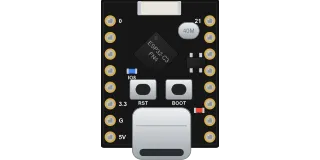
Bottom view (the header and sticker side), Grove connector at the bottom edge; USB-C on the same end, G39 button and RGB LED on the opposite side.
BuyCompareDownload PNG- Chip
- ESP32-PICO-D4
- Logic
- 3.3 V
- Power
- USB-C 4.75-5.25 V5V (header or Grove) 4.75-5.25 V
- Defaults in arduino-esp32 (M5Stack-ATOM)
- I2C: SDA 26, SCL 32SPI: MOSI 33, MISO 23, SCK 22, SS 19UART: TX 1, RX 3
Which M5Stack ATOM Lite pins are safe to use
Free to use
GPIO19, GPIO21-23, GPIO25, GPIO26, GPIO32, GPIO33
Important
- 3.3 V logic, don't put 5 V on the GPIO.
- The drawing is a bottom view: this is how the pins look on the case. The button, RGB LED and IR LED are on the other side and are not broken out.
- Button: G39, input only, 4.7 kΩ pull-up to 3.3 V on the board, pressing gives a low level.
- SK6812 RGB LED on G27, 5 V supply. IR LED on G12 through 22 Ω; G12 is the strapping pin MTDI, a low level at reset selects 3.3 V flash.
- SPI in arduino-esp32 (M5Stack-ATOM board): SCK G22, MISO G23, MOSI G33, SS G19. The M5Stack pinout labels it differently: MOSI G19, CLK G23, MISO G33.
- I2C in arduino-esp32: Wire on Grove (SDA G26, SCL G32). The M5Stack pinout shows another pair: SCL G21, SDA G25.
- USB-UART on CH552T, M5Stack docs say the FTDI VCP driver is needed.
- Header positions are taken from the dimension drawing, Grove is drawn approximately.
- The 5V of the header and Grove comes from USB through a 1N5819 diode and a 1 A resettable fuse. 3.3 V comes from the SY8089A DC-DC.
All pins
| Label | Number | Functions | Limits | Check |
|---|---|---|---|---|
| 3V3 | 3.3 V | power output | verifiedSY8089A DC-DC output. | |
| G22 | GPIO22 | interruptPWM (LEDC)SPI SCK | not 5 V tolerant | verified |
| G19 | GPIO19 | interruptPWM (LEDC)SPI SSSPI MOSI (M5Stack pinout) | not 5 V tolerant | verified |
| G23 | GPIO23 | interruptPWM (LEDC)SPI MISOSPI CLK (M5Stack pinout)ADC1_CH6 via GPIO34 | not 5 V tolerant | verifiedPer the schematic this pin is also connected through 100 Ω to GPIO34 (input only, ADC1_CH6): the voltage on G23 can be read with analogRead(34). |
| G33 | GPIO33 | interruptPWM (LEDC)ADC1_CH5TOUCH8RTC_GPIO8XTAL_32K_N (32 kHz crystal)SPI MOSISPI MISO (M5Stack pinout) | not 5 V tolerant | verified |
| G21 | GPIO21 | interruptPWM (LEDC)I2C SCL (M5Stack pinout) | not 5 V tolerant | verified |
| G25 | GPIO25 | interruptPWM (LEDC)ADC2_CH8RTC_GPIO6DAC1I2C SDA (M5Stack pinout) | ADC2 doesn't work with Wi-Fi onnot 5 V tolerant | verifiedADC2: while Wi-Fi is running, analogRead on this pin doesn't work. For ADC with Wi-Fi, use ADC1 (GPIO32–39). |
| 5V | 5 V | power inputpower output | verified5 V from USB through a diode and a 1 A fuse; you can feed 5 V in here. | |
| G | Ground | verified | ||
| G | Ground | verified | ||
| 5V | 5 V | power inputpower output | verifiedThe same 5 V net as on the header. | |
| G26 | GPIO26 | interruptPWM (LEDC)ADC2_CH9RTC_GPIO7DAC2I2C SDA (Wire) | ADC2 doesn't work with Wi-Fi onnot 5 V tolerant | verifiedADC2: while Wi-Fi is running, analogRead on this pin doesn't work. For ADC with Wi-Fi, use ADC1 (GPIO32–39). |
| G32 | GPIO32 | interruptPWM (LEDC)ADC1_CH4TOUCH9RTC_GPIO9XTAL_32K_P (32 kHz crystal)I2C SCL (Wire) | not 5 V tolerant | verified |
Sources
Every pin is verified against the manufacturer's documents.
- M5Stack ATOM Lite (docs.m5stack.com)user guide, checked 20.10.2026ESP32-PICO-D4, 4 MB flash, 24×24×9.5 mm case, 5 V 500 mA supply, pins G19, G21, G22, G23, G25, G33, Grove, SK6812 on G27, button G39, IR on G12, FTDI VCP driver
- M5Stack ATOM Lite PinMap (C008_PinMap_01.jpg)manufacturer pinout, checked 20.10.2026bottom view: left 3V3, G22, G19, G23, G33; right G21, G25, 5V, GND; Grove GND, 5V, G26, G32; SPI MOSI G19, CLK G23, MISO G33; I2C SCL G21, SDA G25
- M5Stack ATOM Lite schematic (image on the product page)schematic, checked 20.10.2026J4: 3V3, IO22, IO19, IO23, IO33; J3: IO21, IO25, 5V (VGROVE), GND; Grove J2: GND, 5V, IO26, IO32; IO23 through 100 Ω to IO34; SK6812 on IO27; button IO39 with a 4.7 kΩ pull-up; IR LED on IO12 through 22 Ω; CH552T, SY8089A, 1N5819, 1 A fuse
- M5Stack ATOM Lite model size (drawing)board drawing, checked 20.10.202624×24×9.5 mm, M2 hole in the center, header rows 15.24 mm apart with 2.54 pitch (measured from the drawing), Grove at the bottom edge
- arduino-esp32: variants/m5stack_atom/pins_arduino.hArduino core, checked 20.10.2026SDA 26, SCL 32, SS 19, MOSI 33, MISO 23, SCK 22, TX 1, RX 3, DAC1 25, DAC2 26
- ESP32 Series Datasheet (Espressif)datasheet, checked 15.10.2026IO MUX and pin functions, ADC1/ADC2, touch, DAC, RTC GPIO, strapping (GPIO0, 2, 5, 12, 15), flash pins GPIO6–11, input-only GPIO34–39
- ESP-IDF: GPIO & RTC GPIO (ESP32)user guide, checked 15.10.2026GPIO6–11 used by flash, GPIO34–39 input only with no pull-ups, strapping pins, GPIO1/3 UART0
- ESP-IDF: ADC Oneshot Mode Driver (ESP32)user guide, checked 15.10.2026ADC2 can't be used while Wi-Fi is running
- arduino-esp32: variants/esp32/pins_arduino.hArduino core, checked 15.10.2026defaults: TX 1, RX 3, SDA 21, SCL 22, SS 5, MOSI 23, MISO 19, SCK 18
Size: 24×24×9.5 mm case; pin positions taken from the M5Stack dimension drawing (bottom view), accuracy about 0.1 mm (approximate).
FAQ
- Which M5Stack ATOM Lite pins are I2C, SPI and UART?
- By default in arduino-esp32 (M5Stack-ATOM): I2C: SDA GPIO26, SCL GPIO32; SPI: MOSI GPIO33, MISO GPIO23, SCK GPIO22, SS GPIO19; UART: TX GPIO1, RX GPIO3.
- Are the M5Stack ATOM Lite pins 5 V tolerant?
- No. The logic is 3.3 V and the pins are not 5 V tolerant: use a divider or a level shifter for 5 V signals.
- Does ADC2 on the M5Stack ATOM Lite work with Wi-Fi on?
- No. ADC2 pins (GPIO25, GPIO26) can't read analog while Wi-Fi is on. With Wi-Fi, use GPIO23, GPIO32, GPIO33 for the ADC.
You might also need
Schematic with this board
schematic builder with the board already placed
Flash this board
upload a sketch or .bin to this board from the browser
Power budget
will the regulator cope and how long the battery lasts
Calculators
LED resistor, voltage divider, battery runtime, 3D print cost, LED strip power supply and pF, nF, µF conversion
Similar boards


Next
- Emotion keychainmy ESP32-C5 project, prototype
- ESP32 music playermy ESP32 project, prototype
- DITHR//CAMmy ESP32 project, prototype
Need firmware or a device built on ESP32? I'll build it to order