Wemos D1 R32 (ESP32 Uno) pinout
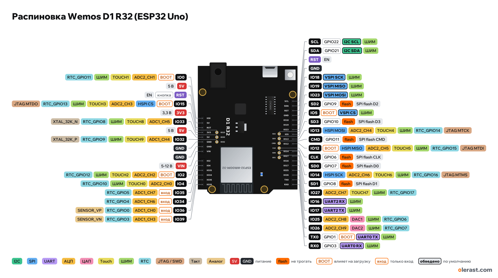
Wemos D1 R32 (ESP32 in the Arduino Uno form factor), ESP32, 3.3 V logic, 68.58×53.34 mm, 41 pins
- IO0BOOTADC2_CH1TOUCH1PWMRTC_GPIO11
- 5V5 V
- RSTbuttonEN
- IO15BOOTHSPI CSADC2_CH3TOUCH3PWMRTC_GPIO13JTAG MTDO
- 3V33.3 V
- IO33ADC1_CH5TOUCH8PWMRTC_GPIO8XTAL_32K_N
- 5V5 V
- IO32ADC1_CH4TOUCH9PWMRTC_GPIO9XTAL_32K_P
- GND
- GND
- VIN5-12 V
- IO2A0BOOTADC2_CH2TOUCH2PWMRTC_GPIO12
- IO4A1ADC2_CH0TOUCH0PWMRTC_GPIO10
- IO35A2inADC1_CH7RTC_GPIO5
- IO34A3inADC1_CH6RTC_GPIO4
- IO36A4inADC1_CH0RTC_GPIO0SENSOR_VP
- IO39A5inADC1_CH3RTC_GPIO3SENSOR_VN
- SCLGPIO22I2C SCLPWM
- SDAGPIO21I2C SDAPWM
- RSTEN
- GND
- IO1813VSPI SCKPWM
- IO1912VSPI MISOPWM
- IO2311VSPI MOSIPWM
- SD2GPIO9flashSPI flash D2
- IO510BOOTVSPI CSPWM
- SD3GPIO10flashSPI flash D3
- IO139HSPI MOSIADC2_CH4TOUCH4PWMRTC_GPIO14JTAG MTCK
- CMDGPIO11flashSPI flash CMD
- IO128BOOTHSPI MISOADC2_CH5TOUCH5PWMRTC_GPIO15JTAG MTDI
- CLKGPIO6flashSPI flash CLK
- SD0GPIO7flashSPI flash D0
- IO147HSPI SCKADC2_CH6TOUCH6PWMRTC_GPIO16JTAG MTMS
- SD1GPIO8flashSPI flash D1
- IO276ADC2_CH7TOUCH7PWMRTC_GPIO17
- IO165UART2 RXPWM
- IO174UART2 TXPWM
- IO253ADC2_CH8DAC1PWMRTC_GPIO6
- IO262ADC2_CH9DAC2PWMRTC_GPIO7
- TX0GPIO11BOOTUART0 TXPWM
- RX0GPIO30UART0 RXPWM
Top view, USB and DC jack on the left, ESP32 module with the antenna to the right, rotated 90° on the diagram.
CompareDownload PNG- Chip
- ESP32, ESP32-WROOM-32
- Logic
- 3.3 V
- Power
- Micro-USB 4.75-5.25 VVIN / DC jack 5-12 V5V
- Defaults in Arduino (ESP32 core, WEMOS D1 R32 board)
- I2C: SDA 21, SCL 22SPI: MOSI 23, MISO 19, SCK 18, SS 5UART: TX 1, RX 3LED: 2
Which Wemos D1 R32 (ESP32 Uno) pins are safe to use
Free to use
GPIO3, GPIO4, GPIO13, GPIO14, GPIO16-19, GPIO21-23, GPIO25-27, GPIO32, GPIO33
Use with care
- GPIO0, GPIO2, GPIO5, GPIO12, GPIO15: strapping: the level at power-up selects the boot mode.
- GPIO1: signal at boot.
- GPIO34-36, GPIO39: input only, no output and no pull-ups.
Leave alone
- GPIO6-11: flash and PSRAM memory.
Important
- 3.3 V logic: do not apply 5 V to IO pins. 5 V Uno shields (with 5 V signals) will damage the ESP32 without a level shifter.
- Pin numbers in the sketch are GPIO numbers, as on the silkscreen (IO18 is 18). The Uno core names D2, D13, A0 also work if you select the WEMOS D1 R32 board.
- A4 and A5 here are IO36 and IO39: input only, I2C does not work on them. I2C is on the separate SDA (IO21) and SCL (IO22) pins.
- IO34, IO35, IO36, IO39 are input only and have no pull-ups or pull-downs.
- ADC2 (IO2, IO4, IO12-IO15, IO25-IO27) cannot read analog input while Wi-Fi is on. With Wi-Fi use IO32-IO39 for analogRead.
- Strapping pins: IO0, IO2, IO5, IO12, IO15. IO12 HIGH at reset breaks boot (module with 3.3 V flash).
- 5 V sits in the place of IOREF: a shield that takes its logic level from IOREF will run at 5 V. For 3.3 V shields check their documentation.
- The six holes SD2, SD3, CMD, CLK, SD0, SD1 next to the digital header are flash lines (GPIO6-11): do not connect them.
- The board runs at 3.3 V: IO pins are not 5 V tolerant. Connect 5 V Uno shields only through a level shifter.
Revisions and clones
- Some boards have D-number labels instead of IO and a different regulator; the pin functions are the same (d1_uno32 variant).
- Wemos D1 (without R32) and D1 R2: same form factor, but ESP8266 and different pins.
All pins
| Label | Number | Functions | Limits | Check |
|---|---|---|---|---|
| SCL | GPIO22 | interruptPWM (LEDC)I2C SCL | not 5 V tolerant | not from manufacturerNo manufacturer document for the board (WEMOS no longer has an R32 page): pin functions follow the d1_uno32 core variant, labels follow the seller's drawing. The IO15, IO33, IO32 holes, the flash line row and the module position come from the drawing, not from a dimensioned plan.Separate I2C SCL pin (GPIO22). On the Uno SCL is tied to A5, here it is not. |
| SDA | GPIO21 | interruptPWM (LEDC)I2C SDA | not 5 V tolerant | not from manufacturerNo manufacturer document for the board (WEMOS no longer has an R32 page): pin functions follow the d1_uno32 core variant, labels follow the seller's drawing. The IO15, IO33, IO32 holes, the flash line row and the module position come from the drawing, not from a dimensioned plan.Separate I2C SDA pin (GPIO21). On the Uno SDA is tied to A4, here it is not. |
| RST | EN: ESP32 reset (low = reset) | onboard pull-up | not from manufacturerNo manufacturer document for the board (WEMOS no longer has an R32 page): pin functions follow the d1_uno32 core variant, labels follow the seller's drawing. The IO15, IO33, IO32 holes, the flash line row and the module position come from the drawing, not from a dimensioned plan.In the place of AREF on the Uno. There is no ADC reference voltage pin here.Labelled on other revisions as: EN, AREF | |
| GND | Ground | not from manufacturerNo manufacturer document for the board (WEMOS no longer has an R32 page): pin functions follow the d1_uno32 core variant, labels follow the seller's drawing. The IO15, IO33, IO32 holes, the flash line row and the module position come from the drawing, not from a dimensioned plan. | ||
| IO18 | GPIO18, Arduino 13 | interruptPWM (LEDC)VSPI SCK | not 5 V tolerant | not from manufacturerNo manufacturer document for the board (WEMOS no longer has an R32 page): pin functions follow the d1_uno32 core variant, labels follow the seller's drawing. The IO15, IO33, IO32 holes, the flash line row and the module position come from the drawing, not from a dimensioned plan. |
| IO19 | GPIO19, Arduino 12 | interruptPWM (LEDC)VSPI MISO | not 5 V tolerant | not from manufacturerNo manufacturer document for the board (WEMOS no longer has an R32 page): pin functions follow the d1_uno32 core variant, labels follow the seller's drawing. The IO15, IO33, IO32 holes, the flash line row and the module position come from the drawing, not from a dimensioned plan. |
| IO23 | GPIO23, Arduino 11 | interruptPWM (LEDC)VSPI MOSI | not 5 V tolerant | not from manufacturerNo manufacturer document for the board (WEMOS no longer has an R32 page): pin functions follow the d1_uno32 core variant, labels follow the seller's drawing. The IO15, IO33, IO32 holes, the flash line row and the module position come from the drawing, not from a dimensioned plan. |
| IO5 | GPIO5, Arduino 10 | interruptPWM (LEDC)VSPI CS (SS) | affects boot (strapping)not 5 V tolerant | not from manufacturerNo manufacturer document for the board (WEMOS no longer has an R32 page): pin functions follow the d1_uno32 core variant, labels follow the seller's drawing. The IO15, IO33, IO32 holes, the flash line row and the module position come from the drawing, not from a dimensioned plan.Strapping: SDIO slave timing. Internal pull-up, don't pull it low during reset. |
| IO13 | GPIO13, Arduino 9 | interruptPWM (LEDC)ADC2_CH4TOUCH4RTC_GPIO14HSPI MOSIJTAG MTCK | ADC2 doesn't work with Wi-Fi onnot 5 V tolerant | not from manufacturerNo manufacturer document for the board (WEMOS no longer has an R32 page): pin functions follow the d1_uno32 core variant, labels follow the seller's drawing. The IO15, IO33, IO32 holes, the flash line row and the module position come from the drawing, not from a dimensioned plan.ADC2: while Wi-Fi is running, analogRead on this pin doesn't work. For ADC with Wi-Fi, use ADC1 (GPIO32–39). |
| IO12 | GPIO12, Arduino 8 | interruptPWM (LEDC)ADC2_CH5TOUCH5RTC_GPIO15HSPI MISOJTAG MTDI | affects boot (strapping)ADC2 doesn't work with Wi-Fi onnot 5 V tolerant | not from manufacturerNo manufacturer document for the board (WEMOS no longer has an R32 page): pin functions follow the d1_uno32 core variant, labels follow the seller's drawing. The IO15, IO33, IO32 holes, the flash line row and the module position come from the drawing, not from a dimensioned plan.MTDI: selects the flash voltage at reset. High = 1.8 V, so a module with 3.3 V flash won't boot. Internal pull-down.ADC2: while Wi-Fi is running, analogRead on this pin doesn't work. For ADC with Wi-Fi, use ADC1 (GPIO32–39). |
| IO14 | GPIO14, Arduino 7 | interruptPWM (LEDC)ADC2_CH6TOUCH6RTC_GPIO16HSPI SCKJTAG MTMS | ADC2 doesn't work with Wi-Fi onnot 5 V tolerant | not from manufacturerNo manufacturer document for the board (WEMOS no longer has an R32 page): pin functions follow the d1_uno32 core variant, labels follow the seller's drawing. The IO15, IO33, IO32 holes, the flash line row and the module position come from the drawing, not from a dimensioned plan.ADC2: while Wi-Fi is running, analogRead on this pin doesn't work. For ADC with Wi-Fi, use ADC1 (GPIO32–39). |
| IO27 | GPIO27, Arduino 6 | interruptPWM (LEDC)ADC2_CH7TOUCH7RTC_GPIO17 | ADC2 doesn't work with Wi-Fi onnot 5 V tolerant | not from manufacturerNo manufacturer document for the board (WEMOS no longer has an R32 page): pin functions follow the d1_uno32 core variant, labels follow the seller's drawing. The IO15, IO33, IO32 holes, the flash line row and the module position come from the drawing, not from a dimensioned plan.ADC2: while Wi-Fi is running, analogRead on this pin doesn't work. For ADC with Wi-Fi, use ADC1 (GPIO32–39). |
| IO16 | GPIO16, Arduino 5 | interruptPWM (LEDC)UART2 RX | not 5 V tolerant | not from manufacturerNo manufacturer document for the board (WEMOS no longer has an R32 page): pin functions follow the d1_uno32 core variant, labels follow the seller's drawing. The IO15, IO33, IO32 holes, the flash line row and the module position come from the drawing, not from a dimensioned plan. |
| IO17 | GPIO17, Arduino 4 | interruptPWM (LEDC)UART2 TX | not 5 V tolerant | not from manufacturerNo manufacturer document for the board (WEMOS no longer has an R32 page): pin functions follow the d1_uno32 core variant, labels follow the seller's drawing. The IO15, IO33, IO32 holes, the flash line row and the module position come from the drawing, not from a dimensioned plan. |
| IO25 | GPIO25, Arduino 3 | interruptPWM (LEDC)ADC2_CH8RTC_GPIO6DAC1 | ADC2 doesn't work with Wi-Fi onnot 5 V tolerant | not from manufacturerNo manufacturer document for the board (WEMOS no longer has an R32 page): pin functions follow the d1_uno32 core variant, labels follow the seller's drawing. The IO15, IO33, IO32 holes, the flash line row and the module position come from the drawing, not from a dimensioned plan.ADC2: while Wi-Fi is running, analogRead on this pin doesn't work. For ADC with Wi-Fi, use ADC1 (GPIO32–39). |
| IO26 | GPIO26, Arduino 2 | interruptPWM (LEDC)ADC2_CH9RTC_GPIO7DAC2 | ADC2 doesn't work with Wi-Fi onnot 5 V tolerant | not from manufacturerNo manufacturer document for the board (WEMOS no longer has an R32 page): pin functions follow the d1_uno32 core variant, labels follow the seller's drawing. The IO15, IO33, IO32 holes, the flash line row and the module position come from the drawing, not from a dimensioned plan.ADC2: while Wi-Fi is running, analogRead on this pin doesn't work. For ADC with Wi-Fi, use ADC1 (GPIO32–39). |
| TX0 | GPIO1, Arduino 1 | interruptPWM (LEDC)UART0 TX | outputs a signal at bootnot 5 V tolerant | not from manufacturerNo manufacturer document for the board (WEMOS no longer has an R32 page): pin functions follow the d1_uno32 core variant, labels follow the seller's drawing. The IO15, IO33, IO32 holes, the flash line row and the module position come from the drawing, not from a dimensioned plan.Prints the bootloader log at boot (115200 baud).Connected to the CH340G bridge: busy during flashing and Serial. |
| RX0 | GPIO3, Arduino 0 | interruptPWM (LEDC)UART0 RX | not 5 V tolerant | not from manufacturerNo manufacturer document for the board (WEMOS no longer has an R32 page): pin functions follow the d1_uno32 core variant, labels follow the seller's drawing. The IO15, IO33, IO32 holes, the flash line row and the module position come from the drawing, not from a dimensioned plan.Connected to the CH340G bridge: busy during flashing and Serial. |
| IO0 | GPIO0 | interruptPWM (LEDC)ADC2_CH1TOUCH1RTC_GPIO11 | affects boot (strapping)ADC2 doesn't work with Wi-Fi onnot 5 V tolerant | not from manufacturerNo manufacturer document for the board (WEMOS no longer has an R32 page): pin functions follow the d1_uno32 core variant, labels follow the seller's drawing. The IO15, IO33, IO32 holes, the flash line row and the module position come from the drawing, not from a dimensioned plan.At reset: low = firmware download mode (BOOT button). Internal pull-up.ADC2: while Wi-Fi is running, analogRead on this pin doesn't work. For ADC with Wi-Fi, use ADC1 (GPIO32–39).In the place of the unused Uno pin. There is no BOOT button: GPIO0 is toggled by auto-flashing through the CH340G. |
| 5V | 5 V | power output | not from manufacturerNo manufacturer document for the board (WEMOS no longer has an R32 page): pin functions follow the d1_uno32 core variant, labels follow the seller's drawing. The IO15, IO33, IO32 holes, the flash line row and the module position come from the drawing, not from a dimensioned plan.In the place of IOREF on the Uno this pin carries 5 V, although the board logic is 3.3 V: a shield that selects its level from IOREF will pick 5 V.Labelled on other revisions as: IOREF | |
| RST | EN: ESP32 reset (low = reset) | onboard pull-uponboard button | not from manufacturerNo manufacturer document for the board (WEMOS no longer has an R32 page): pin functions follow the d1_uno32 core variant, labels follow the seller's drawing. The IO15, IO33, IO32 holes, the flash line row and the module position come from the drawing, not from a dimensioned plan.The RESET button on the board shorts it to ground.Labelled on other revisions as: EN, RESET | |
| 3V3 | 3.3 V | power inputpower output | not from manufacturerNo manufacturer document for the board (WEMOS no longer has an R32 page): pin functions follow the d1_uno32 core variant, labels follow the seller's drawing. The IO15, IO33, IO32 holes, the flash line row and the module position come from the drawing, not from a dimensioned plan.3.3 V regulator output. The ESP32 is powered from it too.Labelled on other revisions as: 3.3V | |
| 5V | 5 V | power inputpower output | not from manufacturerNo manufacturer document for the board (WEMOS no longer has an R32 page): pin functions follow the d1_uno32 core variant, labels follow the seller's drawing. The IO15, IO33, IO32 holes, the flash line row and the module position come from the drawing, not from a dimensioned plan.5 V from USB or from the regulator fed by VIN. | |
| GND | Ground | not from manufacturerNo manufacturer document for the board (WEMOS no longer has an R32 page): pin functions follow the d1_uno32 core variant, labels follow the seller's drawing. The IO15, IO33, IO32 holes, the flash line row and the module position come from the drawing, not from a dimensioned plan. | ||
| GND | Ground | not from manufacturerNo manufacturer document for the board (WEMOS no longer has an R32 page): pin functions follow the d1_uno32 core variant, labels follow the seller's drawing. The IO15, IO33, IO32 holes, the flash line row and the module position come from the drawing, not from a dimensioned plan. | ||
| VIN | 9 V | power input | not from manufacturerNo manufacturer document for the board (WEMOS no longer has an R32 page): pin functions follow the d1_uno32 core variant, labels follow the seller's drawing. The IO15, IO33, IO32 holes, the flash line row and the module position come from the drawing, not from a dimensioned plan.5-12 V input (per the seller), the same as the DC jack.Labelled on other revisions as: VN | |
| IO2 | GPIO2, Arduino A0 | interruptPWM (LEDC)ADC2_CH2TOUCH2RTC_GPIO12 | affects boot (strapping)ADC2 doesn't work with Wi-Fi onnot 5 V tolerant | not from manufacturerNo manufacturer document for the board (WEMOS no longer has an R32 page): pin functions follow the d1_uno32 core variant, labels follow the seller's drawing. The IO15, IO33, IO32 holes, the flash line row and the module position come from the drawing, not from a dimensioned plan.At reset it must be low or floating for download mode. Internal pull-down.ADC2: while Wi-Fi is running, analogRead on this pin doesn't work. For ADC with Wi-Fi, use ADC1 (GPIO32–39).On-board LED (LED_BUILTIN = 2 in the core). Strapping pin: keep low or floating during flashing. |
| IO4 | GPIO4, Arduino A1 | interruptPWM (LEDC)ADC2_CH0TOUCH0RTC_GPIO10 | ADC2 doesn't work with Wi-Fi onnot 5 V tolerant | not from manufacturerNo manufacturer document for the board (WEMOS no longer has an R32 page): pin functions follow the d1_uno32 core variant, labels follow the seller's drawing. The IO15, IO33, IO32 holes, the flash line row and the module position come from the drawing, not from a dimensioned plan.ADC2: while Wi-Fi is running, analogRead on this pin doesn't work. For ADC with Wi-Fi, use ADC1 (GPIO32–39). |
| IO35 | GPIO35, Arduino A2 | interruptADC1_CH7RTC_GPIO5 | input onlynot 5 V tolerant | not from manufacturerNo manufacturer document for the board (WEMOS no longer has an R32 page): pin functions follow the d1_uno32 core variant, labels follow the seller's drawing. The IO15, IO33, IO32 holes, the flash line row and the module position come from the drawing, not from a dimensioned plan.Input only: no output and no internal pull-ups. |
| IO34 | GPIO34, Arduino A3 | interruptADC1_CH6RTC_GPIO4 | input onlynot 5 V tolerant | not from manufacturerNo manufacturer document for the board (WEMOS no longer has an R32 page): pin functions follow the d1_uno32 core variant, labels follow the seller's drawing. The IO15, IO33, IO32 holes, the flash line row and the module position come from the drawing, not from a dimensioned plan.Input only: no output and no internal pull-ups. |
| IO36 | GPIO36, Arduino A4 | interruptADC1_CH0RTC_GPIO0SENSOR_VP | input onlynot 5 V tolerant | not from manufacturerNo manufacturer document for the board (WEMOS no longer has an R32 page): pin functions follow the d1_uno32 core variant, labels follow the seller's drawing. The IO15, IO33, IO32 holes, the flash line row and the module position come from the drawing, not from a dimensioned plan.Input only: no output and no internal pull-ups.On the Uno A4 carries I2C (SDA). Here it is the input-only GPIO36: I2C is on the SDA and SCL pins at the top. |
| IO39 | GPIO39, Arduino A5 | interruptADC1_CH3RTC_GPIO3SENSOR_VN | input onlynot 5 V tolerant | not from manufacturerNo manufacturer document for the board (WEMOS no longer has an R32 page): pin functions follow the d1_uno32 core variant, labels follow the seller's drawing. The IO15, IO33, IO32 holes, the flash line row and the module position come from the drawing, not from a dimensioned plan.Input only: no output and no internal pull-ups.On the Uno A5 carries I2C (SCL). Here it is the input-only GPIO39. |
| IO15 | GPIO15 | interruptPWM (LEDC)ADC2_CH3TOUCH3RTC_GPIO13HSPI CSJTAG MTDO | affects boot (strapping)ADC2 doesn't work with Wi-Fi onnot 5 V tolerant | not from manufacturerNo manufacturer document for the board (WEMOS no longer has an R32 page): pin functions follow the d1_uno32 core variant, labels follow the seller's drawing. The IO15, IO33, IO32 holes, the flash line row and the module position come from the drawing, not from a dimensioned plan.MTDO: low at reset silences the bootloader log on UART0. Internal pull-up.ADC2: while Wi-Fi is running, analogRead on this pin doesn't work. For ADC with Wi-Fi, use ADC1 (GPIO32–39). |
| IO33 | GPIO33 | interruptPWM (LEDC)ADC1_CH5TOUCH8RTC_GPIO8XTAL_32K_N (32 kHz crystal) | not 5 V tolerant | not from manufacturerNo manufacturer document for the board (WEMOS no longer has an R32 page): pin functions follow the d1_uno32 core variant, labels follow the seller's drawing. The IO15, IO33, IO32 holes, the flash line row and the module position come from the drawing, not from a dimensioned plan. |
| IO32 | GPIO32 | interruptPWM (LEDC)ADC1_CH4TOUCH9RTC_GPIO9XTAL_32K_P (32 kHz crystal) | not 5 V tolerant | not from manufacturerNo manufacturer document for the board (WEMOS no longer has an R32 page): pin functions follow the d1_uno32 core variant, labels follow the seller's drawing. The IO15, IO33, IO32 holes, the flash line row and the module position come from the drawing, not from a dimensioned plan. |
| SD2 | GPIO9 | SPI flash D2 (HD) | used by flash, do not usenot 5 V tolerant | not from manufacturerNo manufacturer document for the board (WEMOS no longer has an R32 page): pin functions follow the d1_uno32 core variant, labels follow the seller's drawing. The IO15, IO33, IO32 holes, the flash line row and the module position come from the drawing, not from a dimensioned plan.Wired to the module's SPI flash. Connect nothing: the board will stop working. |
| SD3 | GPIO10 | SPI flash D3 (WP) | used by flash, do not usenot 5 V tolerant | not from manufacturerNo manufacturer document for the board (WEMOS no longer has an R32 page): pin functions follow the d1_uno32 core variant, labels follow the seller's drawing. The IO15, IO33, IO32 holes, the flash line row and the module position come from the drawing, not from a dimensioned plan.Wired to the module's SPI flash. Connect nothing: the board will stop working. |
| CMD | GPIO11 | SPI flash CMD (CS) | used by flash, do not usenot 5 V tolerant | not from manufacturerNo manufacturer document for the board (WEMOS no longer has an R32 page): pin functions follow the d1_uno32 core variant, labels follow the seller's drawing. The IO15, IO33, IO32 holes, the flash line row and the module position come from the drawing, not from a dimensioned plan.Wired to the module's SPI flash. Connect nothing: the board will stop working. |
| CLK | GPIO6 | SPI flash CLK | used by flash, do not usenot 5 V tolerant | not from manufacturerNo manufacturer document for the board (WEMOS no longer has an R32 page): pin functions follow the d1_uno32 core variant, labels follow the seller's drawing. The IO15, IO33, IO32 holes, the flash line row and the module position come from the drawing, not from a dimensioned plan.Wired to the module's SPI flash. Connect nothing: the board will stop working. |
| SD0 | GPIO7 | SPI flash D0 (SDO) | used by flash, do not usenot 5 V tolerant | not from manufacturerNo manufacturer document for the board (WEMOS no longer has an R32 page): pin functions follow the d1_uno32 core variant, labels follow the seller's drawing. The IO15, IO33, IO32 holes, the flash line row and the module position come from the drawing, not from a dimensioned plan.Wired to the module's SPI flash. Connect nothing: the board will stop working. |
| SD1 | GPIO8 | SPI flash D1 (SDI) | used by flash, do not usenot 5 V tolerant | not from manufacturerNo manufacturer document for the board (WEMOS no longer has an R32 page): pin functions follow the d1_uno32 core variant, labels follow the seller's drawing. The IO15, IO33, IO32 holes, the flash line row and the module position come from the drawing, not from a dimensioned plan.Wired to the module's SPI flash. Connect nothing: the board will stop working. |
Sources
Not verified against the manufacturer: 41 of 41 pins. The pin card says what confirms each one and where sources disagree.
- arduino-esp32: variants/d1_uno32/pins_arduino.h (WEMOS D1 R32 board)Arduino core, checked 20.10.2026D0 = 3, D1 = 1, D2 = 26, D3 = 25, D4 = 17, D5 = 16, D6 = 27, D7 = 14, D8 = 12, D9 = 13, D10 = 5, D11 = 23, D12 = 19, D13 = 18; A0 = 2, A1 = 4, A2 = 35, A3 = 34, A4 = 36, A5 = 39; SDA 21, SCL 22; SPI 23, 19, 18, SS 5; LED_BUILTIN = 2
- Bot'n Roll: WEMOS D1 R32 W/ESP32 UNO R3 Pinout (pinout drawing pinOut-R32)third-party source, checked 20.10.2026silkscreen: SCL, SDA, RST, GND, IO18, IO19, IO23, IO5, IO13, IO12, IO14, IO27, IO16, IO17, IO25, IO26, TX0, RX0; IO0, 5V, RST, 3V3, 5V, GND, GND, VIN; IO2, IO4, IO35, IO34, IO36, IO39; three holes IO15, IO33, IO32 by the power header; six holes SD2, SD3, CMD, CLK, SD0, SD1 by the digital header; ESP32-WROOM-32, micro-USB, DC 5-12 V, 4 MB flash
- Arduino UNO R3: Eagle files UNO-TH_Rev3e (Uno outline and connectors, shared by boards of this size)board drawing, checked 20.10.2026size 68.58×53.34 mm, header pad centers, holes
- ESP32 Series Datasheet (Espressif)datasheet, checked 15.10.2026IO MUX and pin functions, ADC1/ADC2, touch, DAC, RTC GPIO, strapping (GPIO0, 2, 5, 12, 15), flash pins GPIO6–11, input-only GPIO34–39
- ESP-IDF: GPIO & RTC GPIO (ESP32)user guide, checked 15.10.2026GPIO6–11 used by flash, GPIO34–39 input only with no pull-ups, strapping pins, GPIO1/3 UART0
- ESP-IDF: ADC Oneshot Mode Driver (ESP32)user guide, checked 15.10.2026ADC2 can't be used while Wi-Fi is running
- arduino-esp32: variants/esp32/pins_arduino.hArduino core, checked 15.10.2026defaults: TX 1, RX 3, SDA 21, SCL 22, SS 5, MOSI 23, MISO 19, SCK 18
Size: outline and headers as on the Uno R3; module, USB and small parts from the seller's drawing.
FAQ
- Which Wemos D1 R32 (ESP32 Uno) pins are I2C, SPI and UART?
- By default in Arduino (ESP32 core, WEMOS D1 R32 board): I2C: SDA GPIO21, SCL GPIO22; SPI: MOSI GPIO23, MISO GPIO19, SCK GPIO18, SS GPIO5; UART: TX GPIO1, RX GPIO3.
- Which pin is the Wemos D1 R32 (ESP32 Uno) LED on?
- LED on IO2 (LED_BUILTIN = 2 in the core).
- Are the Wemos D1 R32 (ESP32 Uno) pins 5 V tolerant?
- No. The logic is 3.3 V and the pins are not 5 V tolerant: use a divider or a level shifter for 5 V signals.
- Does ADC2 on the Wemos D1 R32 (ESP32 Uno) work with Wi-Fi on?
- No. ADC2 pins (GPIO0, GPIO2, GPIO4, GPIO12-15, GPIO25-27) can't read analog while Wi-Fi is on. With Wi-Fi, use GPIO32-36, GPIO39 for the ADC.
You might also need
Schematic with this board
schematic builder with the board already placed
Flash this board
upload a sketch or .bin to this board from the browser
Power budget
will the regulator cope and how long the battery lasts
Calculators
LED resistor, voltage divider, battery runtime, 3D print cost, LED strip power supply and pF, nF, µF conversion
Similar boards
Next
- Emotion keychainmy ESP32 project, prototype
- ESP32 music playermy ESP32 project, prototype
- DITHR//CAMmy ESP32 project, prototype
Need firmware or a device built on ESP32? I'll build it to order