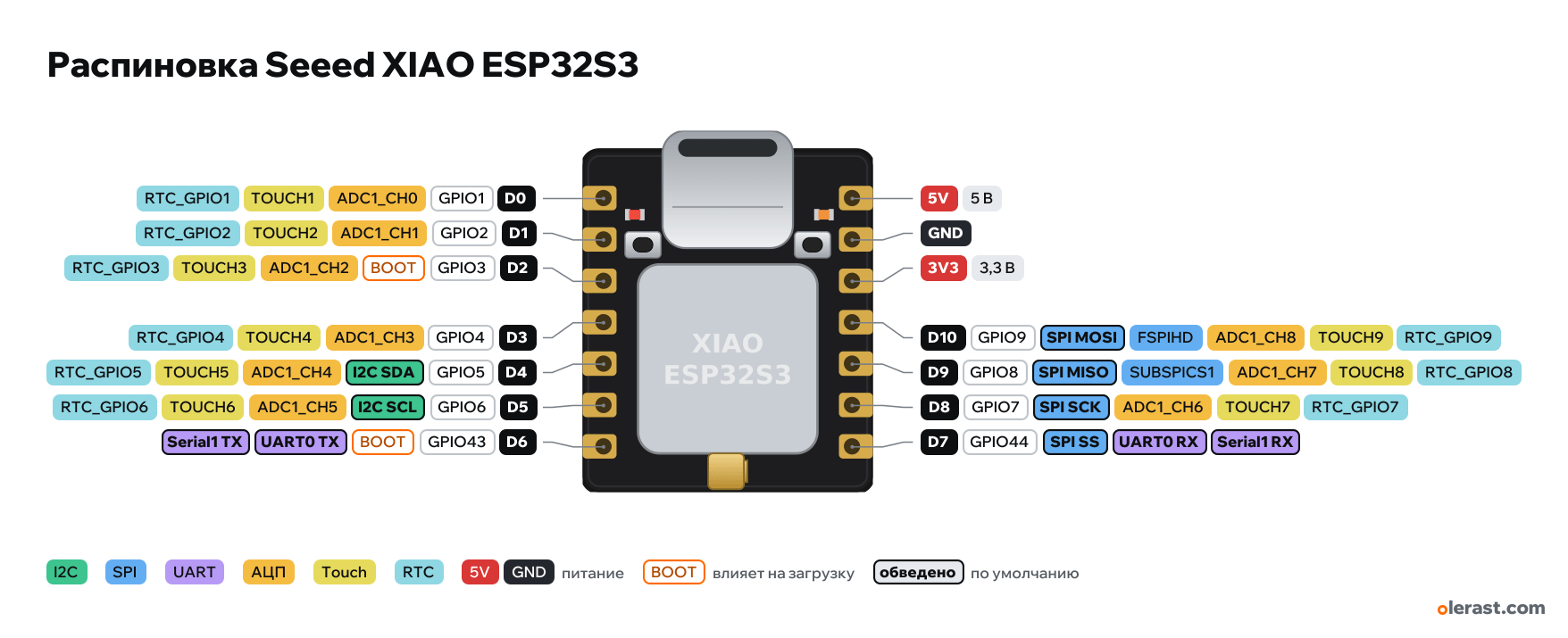
Seeed XIAO ESP32S3 pinout
Seeed XIAO ESP32S3, ESP32-S3, 3.3 V logic, 17.8×20.975 mm, 14 pins
verified17.10.2026
Top view, USB-C at the top.
BuyCompareDownload PNG- Chip
- ESP32-S3, ESP32-S3R8 + 8 MB flash
- Logic
- 3.3 V
- Power
- USB-C 4.75-5.25 V5V 4.75-5.25 VLi-ion 3.7 V (BAT+ and BAT− pads on the back) 3.3-4.2 V
- Defaults in arduino-esp32 (XIAO_ESP32S3)
- I2C: SDA 5, SCL 6SPI: MOSI 9, MISO 8, SCK 7, SS 44UART: TX 43, RX 44LED: 21
Which Seeed XIAO ESP32S3 pins are safe to use
Free to use
GPIO1, GPIO2, GPIO4-9, GPIO44
Use with care
- GPIO3: strapping: the level at power-up selects the boot mode.
- GPIO43: signal at boot.
Important
- 3.3 V logic, don't put 5 V on the GPIO.
- The labels D0…D10, 5V, GND, 3V3 are printed on the back (the screen is on top), the Arduino numbers are D0…D10, not GPIO.
- Orange LED on GPIO21 (lit when LOW), not routed to the header. On the XIAO ESP32S3 Sense, GPIO21 is also the microSD card CS.
- No strapping pins on the header (GPIO0 is the BOOT button).
- ADC: D0-D5 (ADC1), D8-D10 (ADC2, may not work with Wi-Fi). Touch: D0-D10, except D6 and D7.
- Sense version: OV2640/OV3660 camera and microSD on the expansion board through the B2B connector, header pins are free.
- The module has 8 MB of PSRAM (Octal): GPIO33-37 are used internally and not routed to the header.
- Placement of small components is approximate, pins and size follow the Seeed footprint.
All pins
| Label | Number | Functions | Limits | Check |
|---|---|---|---|---|
| D0 | GPIO1, Arduino D0 (1) | interruptPWM (LEDC)ADC1_CH0TOUCH1RTC_GPIO1 | not 5 V tolerant | verified |
| D1 | GPIO2, Arduino D1 (2) | interruptPWM (LEDC)ADC1_CH1TOUCH2RTC_GPIO2 | not 5 V tolerant | verified |
| D2 | GPIO3, Arduino D2 (3) | interruptPWM (LEDC)ADC1_CH2TOUCH3RTC_GPIO3 | not 5 V tolerantaffects boot (strapping) | verifiedStrapping: JTAG signal source selection. Floating by default, no effect unless the eFuse was changed. |
| D3 | GPIO4, Arduino D3 (4) | interruptPWM (LEDC)ADC1_CH3TOUCH4RTC_GPIO4 | not 5 V tolerant | verified |
| D4 | GPIO5, Arduino D4 (5) | interruptPWM (LEDC)ADC1_CH4TOUCH5RTC_GPIO5I2C SDA | not 5 V tolerant | verified |
| D5 | GPIO6, Arduino D5 (6) | interruptPWM (LEDC)ADC1_CH5TOUCH6RTC_GPIO6I2C SCL | not 5 V tolerant | verified |
| D6 | GPIO43, Arduino D6 (43) | interruptPWM (LEDC)UART0 TXSerial1 TX | not 5 V tolerantoutputs a signal at boot | verified |
| 5V | 5 V | power inputpower output | verified5 V from USB-C (output) or a 5 V input. Nothing here when running from a battery. | |
| GND | Ground | verified | ||
| 3V3 | 3.3 V | power output | verifiedBoard 3.3 V regulator output. | |
| D10 | GPIO9, Arduino D10 (9) | interruptPWM (LEDC)ADC1_CH8TOUCH9RTC_GPIO9FSPIHDSPI MOSI | not 5 V tolerant | verified |
| D9 | GPIO8, Arduino D9 (8) | interruptPWM (LEDC)ADC1_CH7TOUCH8RTC_GPIO8SUBSPICS1SPI MISO | not 5 V tolerant | verified |
| D8 | GPIO7, Arduino D8 (7) | interruptPWM (LEDC)ADC1_CH6TOUCH7RTC_GPIO7SPI SCK | not 5 V tolerant | verified |
| D7 | GPIO44, Arduino D7 (44) | interruptPWM (LEDC)UART0 RXSerial1 RXSPI SS | not 5 V tolerant | verified |
Sources
Every pin is verified against the manufacturer's documents.
- Seeed Studio Wiki: Getting Started with Seeed XIAO ESP32S3user guide, checked 17.10.2026D0-D10 → GPIO1-6, 43, 44, 7, 8, 9; orange LED on GPIO21; BOOT button (GPIO0); 21×17.8 mm
- Seeed OPL_Kicad_Library: XIAO-ESP32-S3-DIP.kicad_modboard drawing, checked 17.10.202614 pins: two rows 15.24 mm apart, pitch 2.54, outline 20.975×17.8 mm, outermost pin 2.93 mm from the USB edge
- arduino-esp32: variants/XIAO_ESP32S3/pins_arduino.hArduino core, checked 17.10.2026D0–D10, LED_BUILTIN 21, TX 43, RX 44, SDA 5, SCL 6, SS 44, MOSI 9, MISO 8, SCK 7
- ESP32-S3 Series Datasheet (Espressif)datasheet, checked 15.10.2026pin functions: ADC1_CH0–9 on GPIO1–10, ADC2_CH0–9 on GPIO11–20, TOUCH1–14, RTC GPIO0–21, USB GPIO19/20, JTAG GPIO39–42, UART0 GPIO43/44, strapping GPIO0/3/45/46
- ESP-IDF: GPIO (ESP32-S3)user guide, checked 15.10.2026GPIO26–32 are used by SPI flash/PSRAM, GPIO33–37 are used on modules with Octal flash/PSRAM, strapping pins, USB
- arduino-esp32: variants/esp32s3/pins_arduino.hArduino core, checked 15.10.2026defaults: TX 43, RX 44, SDA 8, SCL 9, SS 10, MOSI 11, MISO 13, SCK 12
Size: per the Seeed KiCad footprint (21×17.8 mm).
FAQ
- Which Seeed XIAO ESP32S3 pins are I2C, SPI and UART?
- By default in arduino-esp32 (XIAO_ESP32S3): I2C: SDA GPIO5, SCL GPIO6; SPI: MOSI GPIO9, MISO GPIO8, SCK GPIO7, SS GPIO44; UART: TX GPIO43, RX GPIO44.
- Which pin is the Seeed XIAO ESP32S3 LED on?
- Orange LED on GPIO21 (lit when LOW).
- Are the Seeed XIAO ESP32S3 pins 5 V tolerant?
- No. The logic is 3.3 V and the pins are not 5 V tolerant: use a divider or a level shifter for 5 V signals.
You might also need
Similar boards
Next
- Emotion keychainmy ESP32-S3 project, prototype
- Troll Botmy ESP32-S3 project, prototype
- olerast PULSEmy ESP32-S3 project, in development
Need firmware or a device built on ESP32? I'll build it to order