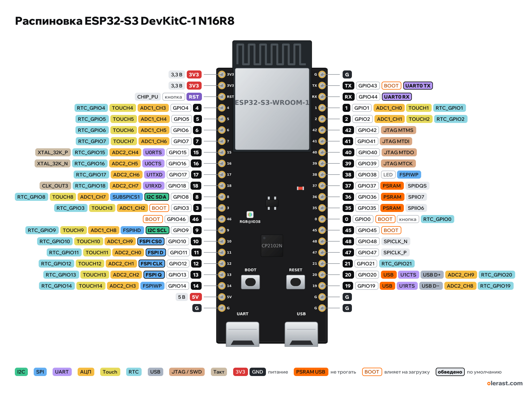
ESP32-S3 DevKitC-1 N16R8 pinout
ESP32-S3-DevKitC-1 v1.1, ESP32-S3, 3.3 V logic, 25.4×62.74 mm, 44 pins
verified15.10.2026
- 3V33.3 V
- 3V33.3 V
- RSTbuttonCHIP_PU
- 4GPIO4ADC1_CH3TOUCH4RTC_GPIO4
- 5GPIO5ADC1_CH4TOUCH5RTC_GPIO5
- 6GPIO6ADC1_CH5TOUCH6RTC_GPIO6
- 7GPIO7ADC1_CH6TOUCH7RTC_GPIO7
- 15GPIO15U0RTSADC2_CH4RTC_GPIO15XTAL_32K_P
- 16GPIO16U0CTSADC2_CH5RTC_GPIO16XTAL_32K_N
- 17GPIO17U1TXDADC2_CH6RTC_GPIO17
- 18GPIO18U1RXDADC2_CH7RTC_GPIO18CLK_OUT3
- 8GPIO8I2C SDASUBSPICS1ADC1_CH7TOUCH8RTC_GPIO8
- 3GPIO3BOOTADC1_CH2TOUCH3RTC_GPIO3
- 46GPIO46BOOT
- 9GPIO9I2C SCLFSPIHDADC1_CH8TOUCH9RTC_GPIO9
- 10GPIO10FSPI CS0ADC1_CH9TOUCH10RTC_GPIO10
- 11GPIO11FSPI DADC2_CH0TOUCH11RTC_GPIO11
- 12GPIO12FSPI CLKADC2_CH1TOUCH12RTC_GPIO12
- 13GPIO13FSPI QADC2_CH2TOUCH13RTC_GPIO13
- 14GPIO14FSPIWPADC2_CH3TOUCH14RTC_GPIO14
- 5V5 V
- G
- G
- TXGPIO43BOOTUART0 TX
- RXGPIO44UART0 RX
- 1GPIO1ADC1_CH0TOUCH1RTC_GPIO1
- 2GPIO2ADC1_CH1TOUCH2RTC_GPIO2
- 42GPIO42JTAG MTMS
- 41GPIO41JTAG MTDI
- 40GPIO40JTAG MTDO
- 39GPIO39JTAG MTCK
- 38GPIO38LEDFSPIWP
- 37GPIO37PSRAMSPIDQS
- 36GPIO36PSRAMSPIIO7
- 35GPIO35PSRAMSPIIO6
- 0GPIO0BOOTbuttonRTC_GPIO0
- 45GPIO45BOOT
- 48GPIO48SPICLK_N
- 47GPIO47SPICLK_P
- 21GPIO21RTC_GPIO21
- 20GPIO20USBU1CTSUSB D+ADC2_CH9RTC_GPIO20
- 19GPIO19USBU1RTSUSB D−ADC2_CH8RTC_GPIO19
- G
- G
Top view, two USB ports at the bottom, module antenna at the top.
BuyCompareDownload PNG- Chip
- ESP32-S3, ESP32-S3-WROOM-1 / -1U (N8, N8R2, N8R8, N16R8…)
- Logic
- 3.3 V
- Power
- USB «UART» (micro-USB, CP2102N) 4.75-5.25 VUSB port "USB" (micro-USB, native USB of the ESP32-S3) 4.75-5.25 V5V 4.75-5.25 V3V3 3-3.6 V
- Defaults in arduino-esp32 (ESP32S3 Dev Module)
- I2C: SDA 8, SCL 9SPI: MOSI 11, MISO 13, SCK 12, SS 10UART: TX 43, RX 44
Which ESP32-S3 DevKitC-1 N16R8 pins are safe to use
Free to use
GPIO1, GPIO2, GPIO4-18, GPIO21, GPIO39-42, GPIO44, GPIO47, GPIO48
Use with care
- GPIO0, GPIO3, GPIO45, GPIO46: strapping: the level at power-up selects the boot mode.
- GPIO19, GPIO20: USB lines: use them and you lose USB flashing and the serial port.
- GPIO38: onboard LED.
- GPIO43: signal at boot.
Leave alone
- GPIO35-37: flash and PSRAM memory.
Important
- 3.3 V logic, don't put 5 V on the GPIO.
- GPIO35, 36, 37 are used by Octal PSRAM/flash on N8R8, N16R8, N32R8 and WROOM-2 modules: don't use them on such boards. The module marking is on its shield.
- Strapping: GPIO0 (BOOT), 3, 45, 46. Keep GPIO45 and 46 low at power-up.
- ADC: ADC1 on GPIO1–10, ADC2 on GPIO11–20 (ADC2 may not work with Wi-Fi).
- The "USB" port is the chip's native USB on GPIO19/20. If you use those pins for something else, this port stops working.
- In arduino-esp32, RGB_BUILTIN points to GPIO48 (v1.0 board). On v1.1 the LED is on GPIO38, so set the pin manually.
- Top pin: 1.40 mm from the edge by the drawing's dimensions, 1.55 mm by the drawing's geometry (0.15 mm discrepancy).
- Small parts (regulator, USB-UART bridge, LEDs) are drawn roughly from the drawing and photos; pins, module, USB and buttons follow the dimension drawing.
- Power it one way only. Both USB ports at once are fine: they serve different purposes and the supply is isolated by diodes.
Revisions and clones
- v1.0: RGB LED on GPIO48, everything else the same.
- "ESP32-S3 N16R8" clones with two USB-C ports often copy the DevKitC-1 pinout, but the jumpers and the LED may differ (many have the RGB on GPIO48). Check the labels.
All pins
| Label | Number | Functions | Limits | Check |
|---|---|---|---|---|
| 3V3 | 3.3 V | power inputpower output | verified | |
| 3V3 | 3.3 V | power inputpower output | verified | |
| RST | CHIP_PU: enable and reset (low = reset) | onboard pull-uponboard button | verifiedRESET button on the board. | |
| 4 | GPIO4 | interruptPWM (LEDC)ADC1_CH3TOUCH4RTC_GPIO4 | not 5 V tolerant | verified |
| 5 | GPIO5 | interruptPWM (LEDC)ADC1_CH4TOUCH5RTC_GPIO5 | not 5 V tolerant | verified |
| 6 | GPIO6 | interruptPWM (LEDC)ADC1_CH5TOUCH6RTC_GPIO6 | not 5 V tolerant | verified |
| 7 | GPIO7 | interruptPWM (LEDC)ADC1_CH6TOUCH7RTC_GPIO7 | not 5 V tolerant | verified |
| 15 | GPIO15 | interruptPWM (LEDC)ADC2_CH4RTC_GPIO15XTAL_32K_PU0RTS | not 5 V tolerantADC2 doesn't work with Wi-Fi on | verifiedADC2: with Wi-Fi on, reading may not work (arbitration with Wi-Fi). Use GPIO1–10 for ADC. |
| 16 | GPIO16 | interruptPWM (LEDC)ADC2_CH5RTC_GPIO16XTAL_32K_NU0CTS | not 5 V tolerantADC2 doesn't work with Wi-Fi on | verifiedADC2: with Wi-Fi on, reading may not work (arbitration with Wi-Fi). Use GPIO1–10 for ADC. |
| 17 | GPIO17 | interruptPWM (LEDC)ADC2_CH6RTC_GPIO17U1TXD | not 5 V tolerantADC2 doesn't work with Wi-Fi on | verifiedADC2: with Wi-Fi on, reading may not work (arbitration with Wi-Fi). Use GPIO1–10 for ADC. |
| 18 | GPIO18 | interruptPWM (LEDC)ADC2_CH7RTC_GPIO18U1RXDCLK_OUT3 | not 5 V tolerantADC2 doesn't work with Wi-Fi on | verifiedADC2: with Wi-Fi on, reading may not work (arbitration with Wi-Fi). Use GPIO1–10 for ADC. |
| 8 | GPIO8 | interruptPWM (LEDC)ADC1_CH7TOUCH8RTC_GPIO8I2C SDASUBSPICS1 | not 5 V tolerant | verified |
| 3 | GPIO3 | interruptPWM (LEDC)ADC1_CH2TOUCH3RTC_GPIO3 | not 5 V tolerantaffects boot (strapping) | verifiedStrapping: JTAG signal source selection. Floating by default, no effect unless the eFuse was changed. |
| 46 | GPIO46 | interruptPWM (LEDC) | not 5 V tolerantaffects boot (strapping) | verifiedStrapping: together with GPIO0 selects the boot mode. Internal pull-down, must be low when booting over UART. |
| 9 | GPIO9 | interruptPWM (LEDC)ADC1_CH8TOUCH9RTC_GPIO9I2C SCLFSPIHD | not 5 V tolerant | verified |
| 10 | GPIO10 | interruptPWM (LEDC)ADC1_CH9TOUCH10RTC_GPIO10FSPI CS0 (SS) | not 5 V tolerant | verified |
| 11 | GPIO11 | interruptPWM (LEDC)ADC2_CH0TOUCH11RTC_GPIO11FSPI D (MOSI) | not 5 V tolerantADC2 doesn't work with Wi-Fi on | verifiedADC2: with Wi-Fi on, reading may not work (arbitration with Wi-Fi). Use GPIO1–10 for ADC. |
| 12 | GPIO12 | interruptPWM (LEDC)ADC2_CH1TOUCH12RTC_GPIO12FSPI CLK (SCK) | not 5 V tolerantADC2 doesn't work with Wi-Fi on | verifiedADC2: with Wi-Fi on, reading may not work (arbitration with Wi-Fi). Use GPIO1–10 for ADC. |
| 13 | GPIO13 | interruptPWM (LEDC)ADC2_CH2TOUCH13RTC_GPIO13FSPI Q (MISO) | not 5 V tolerantADC2 doesn't work with Wi-Fi on | verifiedADC2: with Wi-Fi on, reading may not work (arbitration with Wi-Fi). Use GPIO1–10 for ADC. |
| 14 | GPIO14 | interruptPWM (LEDC)ADC2_CH3TOUCH14RTC_GPIO14FSPIWP | not 5 V tolerantADC2 doesn't work with Wi-Fi on | verifiedADC2: with Wi-Fi on, reading may not work (arbitration with Wi-Fi). Use GPIO1–10 for ADC. |
| 5V | 5 V | power inputpower output | verified | |
| G | Ground | verified | ||
| G | Ground | verified | ||
| TX | GPIO43 | interruptPWM (LEDC)UART0 TX | not 5 V tolerantoutputs a signal at boot | verifiedConnected to the CP2102N ("UART" port). |
| RX | GPIO44 | interruptPWM (LEDC)UART0 RX | not 5 V tolerant | verifiedConnected to the CP2102N ("UART" port). |
| 1 | GPIO1 | interruptPWM (LEDC)ADC1_CH0TOUCH1RTC_GPIO1 | not 5 V tolerant | verified |
| 2 | GPIO2 | interruptPWM (LEDC)ADC1_CH1TOUCH2RTC_GPIO2 | not 5 V tolerant | verified |
| 42 | GPIO42 | interruptPWM (LEDC)JTAG MTMS | not 5 V tolerant | verified |
| 41 | GPIO41 | interruptPWM (LEDC)JTAG MTDI | not 5 V tolerant | verified |
| 40 | GPIO40 | interruptPWM (LEDC)JTAG MTDO | not 5 V tolerant | verified |
| 39 | GPIO39 | interruptPWM (LEDC)JTAG MTCK | not 5 V tolerant | verified |
| 38 | GPIO38 | interruptPWM (LEDC)FSPIWP | not 5 V tolerantonboard LED | verifiedv1.1: addressable RGB LED (SK68XXMINI-HS) on the board, labeled "RGB@IO38". On v1.0 it was on GPIO48. |
| 37 | GPIO37 | interruptPWM (LEDC)SPIDQS (Octal) | not 5 V tolerantused by PSRAM, do not use | verifiedUsed on modules with octal PSRAM or flash (N8R8, N16R8, N32R8). Do not use on such modules. |
| 36 | GPIO36 | interruptPWM (LEDC)SPIIO7 (Octal) | not 5 V tolerantused by PSRAM, do not use | verifiedUsed on modules with octal PSRAM or flash (N8R8, N16R8, N32R8). Do not use on such modules. |
| 35 | GPIO35 | interruptPWM (LEDC)SPIIO6 (Octal) | not 5 V tolerantused by PSRAM, do not use | verifiedUsed on modules with octal PSRAM or flash (N8R8, N16R8, N32R8). Do not use on such modules. |
| 0 | GPIO0 | interruptPWM (LEDC)RTC_GPIO0 | not 5 V tolerantaffects boot (strapping)onboard button | verifiedAt reset: low = firmware download mode (BOOT button).BOOT button on the board. |
| 45 | GPIO45 | interruptPWM (LEDC) | not 5 V tolerantaffects boot (strapping) | verifiedStrapping: VDD_SPI voltage. Internal pull-down, do not pull high at reset. |
| 48 | GPIO48 | interruptPWM (LEDC)SPICLK_N | not 5 V tolerant | verifiedOn v1.0 the RGB LED is connected here (free on v1.1). |
| 47 | GPIO47 | interruptPWM (LEDC)SPICLK_P | not 5 V tolerant | verified |
| 21 | GPIO21 | interruptPWM (LEDC)RTC_GPIO21 | not 5 V tolerant | verified |
| 20 | GPIO20 | interruptPWM (LEDC)ADC2_CH9RTC_GPIO20USB D+U1CTS | not 5 V tolerantADC2 doesn't work with Wi-Fi onUSB line | verifiedADC2: with Wi-Fi on, reading may not work (arbitration with Wi-Fi). Use GPIO1–10 for ADC.Built-in USB lines (the USB port on the board). If you use them as GPIO, USB disappears.Connected to the board "USB" port (D+). |
| 19 | GPIO19 | interruptPWM (LEDC)ADC2_CH8RTC_GPIO19USB D−U1RTS | not 5 V tolerantADC2 doesn't work with Wi-Fi onUSB line | verifiedADC2: with Wi-Fi on, reading may not work (arbitration with Wi-Fi). Use GPIO1–10 for ADC.Built-in USB lines (the USB port on the board). If you use them as GPIO, USB disappears.Connected to the board "USB" port (D−). |
| G | Ground | verified | ||
| G | Ground | verified |
Sources
Every pin is verified against the manufacturer's documents.
- ESP32-S3-DevKitC-1 v1.1 User Guide (Espressif), Header Block J1/J3user guide, checked 15.10.2026functions of all 44 pins, RGB LED GPIO38 (v1.1) / GPIO48 (v1.0), GPIO35–37 taken on modules with Octal flash/PSRAM, two USB
- ESP32-S3-DevKitC-1 V1.1 dimensions (DXF/PDF, 2022-04-29)board drawing, checked 15.10.2026board 25.4×62.74 mm, rows at x 1.27 and 24.13, 2.54 pitch, bottom pin 8.00 mm from the bottom edge, silkscreen
- ESP32-S3-DevKitC-1 V1.1 schematic (2022-11-30)schematic, checked 15.10.2026CP2102N, SGM2212-3.3, two micro-USB, SK68XXMINI-HS
- ESP32-S3 Series Datasheet (Espressif)datasheet, checked 15.10.2026pin functions: ADC1_CH0–9 on GPIO1–10, ADC2_CH0–9 on GPIO11–20, TOUCH1–14, RTC GPIO0–21, USB GPIO19/20, JTAG GPIO39–42, UART0 GPIO43/44, strapping GPIO0/3/45/46
- ESP-IDF: GPIO (ESP32-S3)user guide, checked 15.10.2026GPIO26–32 are used by SPI flash/PSRAM, GPIO33–37 are used on modules with Octal flash/PSRAM, strapping pins, USB
- arduino-esp32: variants/esp32s3/pins_arduino.hArduino core, checked 15.10.2026defaults: TX 43, RX 44, SDA 8, SCL 9, SS 10, MOSI 11, MISO 13, SCK 12
Size: from the Espressif drawing (about 62.84 by the drawing's own geometry).
FAQ
- Which ESP32-S3 DevKitC-1 N16R8 pins are I2C, SPI and UART?
- By default in arduino-esp32 (ESP32S3 Dev Module): I2C: SDA GPIO8, SCL GPIO9; SPI: MOSI GPIO11, MISO GPIO13, SCK GPIO12, SS GPIO10; UART: TX GPIO43, RX GPIO44.
- Which pin is the ESP32-S3 DevKitC-1 N16R8 LED on?
- SK68XXMINI-HS RGB LED on GPIO38 (v1.1).
- Are the ESP32-S3 DevKitC-1 N16R8 pins 5 V tolerant?
- No. The logic is 3.3 V and the pins are not 5 V tolerant: use a divider or a level shifter for 5 V signals.
- Does ADC2 on the ESP32-S3 DevKitC-1 N16R8 work with Wi-Fi on?
- No. ADC2 pins (GPIO11-20) can't read analog while Wi-Fi is on. With Wi-Fi, use GPIO1-10 for the ADC.
You might also need
Similar boards
Next
- Emotion keychainmy ESP32-S3 project, prototype
- Troll Botmy ESP32-S3 project, prototype
- olerast PULSEmy ESP32-S3 project, in development
Need firmware or a device built on ESP32? I'll build it to order