Wemos S2 Mini (ESP32-S2) pinout
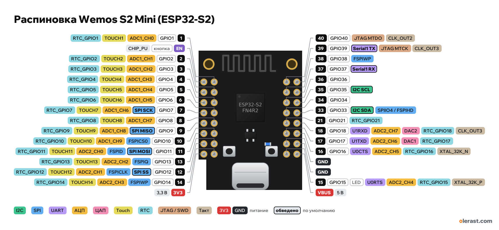
WEMOS LOLIN S2 Mini (ESP32-S2), ESP32-S2, 3.3 V logic, 25.4×34.3 mm, 32 pins
verified17.10.2026
- 1GPIO1ADC1_CH0TOUCH1RTC_GPIO1
- ENbuttonCHIP_PU
- 2GPIO2ADC1_CH1TOUCH2RTC_GPIO2
- 3GPIO3ADC1_CH2TOUCH3RTC_GPIO3
- 4GPIO4ADC1_CH3TOUCH4RTC_GPIO4
- 5GPIO5ADC1_CH4TOUCH5RTC_GPIO5
- 6GPIO6ADC1_CH5TOUCH6RTC_GPIO6
- 7GPIO7SPI SCKADC1_CH6TOUCH7RTC_GPIO7
- 8GPIO8ADC1_CH7TOUCH8RTC_GPIO8
- 9GPIO9SPI MISOADC1_CH8TOUCH9RTC_GPIO9
- 10GPIO10FSPICS0ADC1_CH9TOUCH10RTC_GPIO10
- 11GPIO11SPI MOSIFSPIDADC2_CH0TOUCH11RTC_GPIO11
- 13GPIO13FSPIQADC2_CH2TOUCH13RTC_GPIO13
- 12GPIO12SPI SSFSPICLKADC2_CH1TOUCH12RTC_GPIO12
- 14GPIO14FSPIWPADC2_CH3TOUCH14RTC_GPIO14
- 3V33.3 V
- 40GPIO40JTAG MTDOCLK_OUT2
- 39GPIO39Serial1 TXJTAG MTCKCLK_OUT3
- 38GPIO38FSPIWP
- 37GPIO37Serial1 RX
- 36GPIO36
- 35GPIO35I2C SCL
- 34GPIO34
- 33GPIO33I2C SDASPIIO4 / FSPIHD
- 21GPIO21RTC_GPIO21
- 18GPIO18U1RXDADC2_CH7DAC2RTC_GPIO18CLK_OUT3
- 17GPIO17U1TXDADC2_CH6DAC1RTC_GPIO17
- 16GPIO16U0CTSADC2_CH5RTC_GPIO16XTAL_32K_N
- GND
- GND
- 15GPIO15LEDU0RTSADC2_CH4RTC_GPIO15XTAL_32K_P
- VBUS5 V
Top view, USB-C at the bottom, antenna at the top.
CompareDownload PNG- Chip
- ESP32-S2
- Logic
- 3.3 V
- Power
- USB-C 4.75-5.25 VVBUS 4.75-5.25 V3V3 3-3.6 V
- Defaults in arduino-esp32 (board "LOLIN S2 Mini")
- I2C: SDA 33, SCL 35SPI: MOSI 11, MISO 9, SCK 7, SS 12UART: TX 39, RX 37LED: 15
Which Wemos S2 Mini (ESP32-S2) pins are safe to use
Free to use
GPIO1-14, GPIO16-18, GPIO21, GPIO33-40
Use with care
- GPIO15: onboard LED.
Important
- 3.3 V logic, don't put 5 V on the GPIO.
- There is no USB-UART bridge: USB-C is the ESP32-S2's own USB. If the program hangs or the port disappears, flash like this: hold 0, press and release RST, release 0.
- The two outer rows match the D1 mini in position: D1 mini shields fit, but the pin functions are different.
- ADC: ADC1 on GPIO1-10, ADC2 on 11-20 (may not work with Wi-Fi). DAC: GPIO17, 18. Touch: GPIO1-14.
- Strapping: GPIO0 (button), 45 and 46 are not broken out to the header.
- Silkscreen labels are GPIO numbers; row positions are taken from photos and the D1 mini, there is no exact row drawing.
Revisions and clones
- "S2 mini" clones copy the board; some have the LED on another GPIO or no PSRAM (ESP32-S2FN4).
All pins
| Label | Number | Functions | Limits | Check |
|---|---|---|---|---|
| EN | CHIP_PU: enable and reset (low = reset) | onboard pull-uponboard button | verifiedRESET button on the board. | |
| 3 | GPIO3 | interruptPWM (LEDC)ADC1_CH2RTC_GPIO3TOUCH3 | not 5 V tolerant | verified |
| 5 | GPIO5 | interruptPWM (LEDC)ADC1_CH4RTC_GPIO5TOUCH5 | not 5 V tolerant | verified |
| 7 | GPIO7 | interruptPWM (LEDC)ADC1_CH6RTC_GPIO7TOUCH7SPI SCK | not 5 V tolerant | verified |
| 9 | GPIO9 | interruptPWM (LEDC)ADC1_CH8RTC_GPIO9TOUCH9SPI MISO | not 5 V tolerant | verified |
| 11 | GPIO11 | interruptPWM (LEDC)ADC2_CH0RTC_GPIO11TOUCH11FSPIDSPI MOSI | ADC2 doesn't work with Wi-Fi onnot 5 V tolerant | verifiedADC2: with Wi-Fi on, reading may not work (arbitration with Wi-Fi). Use GPIO1–10 for ADC. |
| 12 | GPIO12 | interruptPWM (LEDC)ADC2_CH1RTC_GPIO12TOUCH12FSPICLKSPI SS | ADC2 doesn't work with Wi-Fi onnot 5 V tolerant | verifiedADC2: with Wi-Fi on, reading may not work (arbitration with Wi-Fi). Use GPIO1–10 for ADC. |
| 3V3 | 3.3 V | power inputpower output | verifiedME6211 regulator output (500 mA) or 3.3 V input. | |
| 1 | GPIO1 | interruptPWM (LEDC)ADC1_CH0RTC_GPIO1TOUCH1 | not 5 V tolerant | verified |
| 2 | GPIO2 | interruptPWM (LEDC)ADC1_CH1RTC_GPIO2TOUCH2 | not 5 V tolerant | verified |
| 4 | GPIO4 | interruptPWM (LEDC)ADC1_CH3RTC_GPIO4TOUCH4 | not 5 V tolerant | verified |
| 6 | GPIO6 | interruptPWM (LEDC)ADC1_CH5RTC_GPIO6TOUCH6 | not 5 V tolerant | verified |
| 8 | GPIO8 | interruptPWM (LEDC)ADC1_CH7RTC_GPIO8TOUCH8 | not 5 V tolerant | verified |
| 10 | GPIO10 | interruptPWM (LEDC)ADC1_CH9RTC_GPIO10TOUCH10FSPICS0 | not 5 V tolerant | verified |
| 13 | GPIO13 | interruptPWM (LEDC)ADC2_CH2RTC_GPIO13TOUCH13FSPIQ | ADC2 doesn't work with Wi-Fi onnot 5 V tolerant | verifiedADC2: with Wi-Fi on, reading may not work (arbitration with Wi-Fi). Use GPIO1–10 for ADC. |
| 14 | GPIO14 | interruptPWM (LEDC)ADC2_CH3RTC_GPIO14TOUCH14FSPIWP | ADC2 doesn't work with Wi-Fi onnot 5 V tolerant | verifiedADC2: with Wi-Fi on, reading may not work (arbitration with Wi-Fi). Use GPIO1–10 for ADC. |
| 40 | GPIO40 | interruptPWM (LEDC)JTAG MTDOCLK_OUT2 | not 5 V tolerant | verifiedJTAG pins. The S2 has no USB-JTAG, JTAG on these pins is not enabled by default: the pins are free. |
| 38 | GPIO38 | interruptPWM (LEDC)FSPIWP | not 5 V tolerant | verified |
| 36 | GPIO36 | interruptPWM (LEDC) | not 5 V tolerant | verified |
| 34 | GPIO34 | interruptPWM (LEDC) | not 5 V tolerant | verified |
| 21 | GPIO21 | interruptPWM (LEDC)RTC_GPIO21 | not 5 V tolerant | verified |
| 17 | GPIO17 | interruptPWM (LEDC)ADC2_CH6RTC_GPIO17DAC1U1TXD | ADC2 doesn't work with Wi-Fi onnot 5 V tolerant | verifiedADC2: with Wi-Fi on, reading may not work (arbitration with Wi-Fi). Use GPIO1–10 for ADC. |
| GND | Ground | verified | ||
| 15 | GPIO15 | interruptPWM (LEDC)ADC2_CH4RTC_GPIO15XTAL_32K_PU0RTS | ADC2 doesn't work with Wi-Fi onnot 5 V tolerantonboard LED | verifiedADC2: with Wi-Fi on, reading may not work (arbitration with Wi-Fi). Use GPIO1–10 for ADC.Blue LED on the board via 2 kΩ to ground: lit when HIGH. LED_BUILTIN = 15. |
| 39 | GPIO39 | interruptPWM (LEDC)JTAG MTCKCLK_OUT3Serial1 TX | not 5 V tolerant | verifiedJTAG pins. The S2 has no USB-JTAG, JTAG on these pins is not enabled by default: the pins are free. |
| 37 | GPIO37 | interruptPWM (LEDC)Serial1 RX | not 5 V tolerant | verified |
| 35 | GPIO35 | interruptPWM (LEDC)I2C SCL | not 5 V tolerant | verified |
| 33 | GPIO33 | interruptPWM (LEDC)SPIIO4 / FSPIHDI2C SDA | not 5 V tolerant | verified |
| 18 | GPIO18 | interruptPWM (LEDC)ADC2_CH7RTC_GPIO18DAC2U1RXDCLK_OUT3 | ADC2 doesn't work with Wi-Fi onnot 5 V tolerant | verifiedADC2: with Wi-Fi on, reading may not work (arbitration with Wi-Fi). Use GPIO1–10 for ADC. |
| 16 | GPIO16 | interruptPWM (LEDC)ADC2_CH5RTC_GPIO16XTAL_32K_NU0CTS | ADC2 doesn't work with Wi-Fi onnot 5 V tolerant | verifiedADC2: with Wi-Fi on, reading may not work (arbitration with Wi-Fi). Use GPIO1–10 for ADC. |
| GND | Ground | verified | ||
| VBUS | 5 V | power inputpower output | verified5 V from USB-C or a 5 V input. |
Sources
Every pin is verified against the manufacturer's documents.
- WEMOS: S2 mini (documentation)user guide, checked 17.10.2026ESP32-S2FN4R2, 4 MB flash, 2 MB PSRAM, USB-C, 27 GPIO, size 34.3×25.4 mm, compatible with D1 mini shields
- WEMOS S2 mini V1.0.0 schematic (KiCad)schematic, checked 17.10.2026nets J2 (EN, IO3, 5, 7, 9, 11, 12, 3V3), J5 (IO1, 2, 4, 6, 8, 10, 13, 14), J4 (IO40, 38, 36, 34, 21, 17, GND, 15), J3 (IO39, 37, 35, 33, 18, 16, GND, VBUS); ME6211C33, EN and IO0 buttons, LED on IO15 via 2 kΩ
- WEMOS S2 mini V1.0.0 dimensionsboard drawing, checked 17.10.202634.30×25.40 mm, cutout in the lower left corner, 2.0 mm holes: 2.5 mm from the edge and 20.4 mm apart
- arduino-esp32: variants/lolin_s2_mini/pins_arduino.hArduino core, checked 17.10.2026LED_BUILTIN 15, TX 39, RX 37, SDA 33, SCL 35, SS 12, MOSI 11, MISO 9, SCK 7, USB VID:PID 303a:80c2
- ESP32-S2 Series Datasheet (Espressif)datasheet, checked 17.10.2026pin functions: ADC1_CH0-9 on GPIO1-10, ADC2_CH0-9 on GPIO11-20, TOUCH1-14, DAC on GPIO17/18, USB OTG GPIO19/20, JTAG GPIO39-42, UART0 GPIO43/44, strapping GPIO0/45/46, GPIO46 input only
- ESP-IDF: GPIO (ESP32-S2)user guide, checked 17.10.2026GPIO26-32 are used by SPI flash and PSRAM, GPIO46 is input only, strapping pins, RTC GPIO0-21
- arduino-esp32: variants/esp32s2/pins_arduino.hArduino core, checked 17.10.2026defaults: TX 43, RX 44, SDA 8, SCL 9, SS 34, MOSI 35, MISO 37, SCK 36
Size: per the Wemos dimension drawing; rows as on the D1 mini, their position taken from photos.
FAQ
- Which Wemos S2 Mini (ESP32-S2) pins are I2C, SPI and UART?
- By default in arduino-esp32 (board "LOLIN S2 Mini"): I2C: SDA GPIO33, SCL GPIO35; SPI: MOSI GPIO11, MISO GPIO9, SCK GPIO7, SS GPIO12; UART: TX GPIO39, RX GPIO37.
- Which pin is the Wemos S2 Mini (ESP32-S2) LED on?
- Blue LED on GPIO15.
- Are the Wemos S2 Mini (ESP32-S2) pins 5 V tolerant?
- No. The logic is 3.3 V and the pins are not 5 V tolerant: use a divider or a level shifter for 5 V signals.
- Does ADC2 on the Wemos S2 Mini (ESP32-S2) work with Wi-Fi on?
- No. ADC2 pins (GPIO11-18) can't read analog while Wi-Fi is on. With Wi-Fi, use GPIO1-10 for the ADC.
You might also need
Schematic with this board
schematic builder with the board already placed
Flash this board
upload a sketch or .bin to this board from the browser
Power budget
will the regulator cope and how long the battery lasts
Calculators
LED resistor, voltage divider, battery runtime, 3D print cost, LED strip power supply and pF, nF, µF conversion
Similar boards
Next
- Emotion keychainmy ESP32-C5 project, prototype
- ESP32 music playermy ESP32 project, prototype
- DITHR//CAMmy ESP32 project, prototype
Need firmware or a device built on ESP32? I'll build it to order