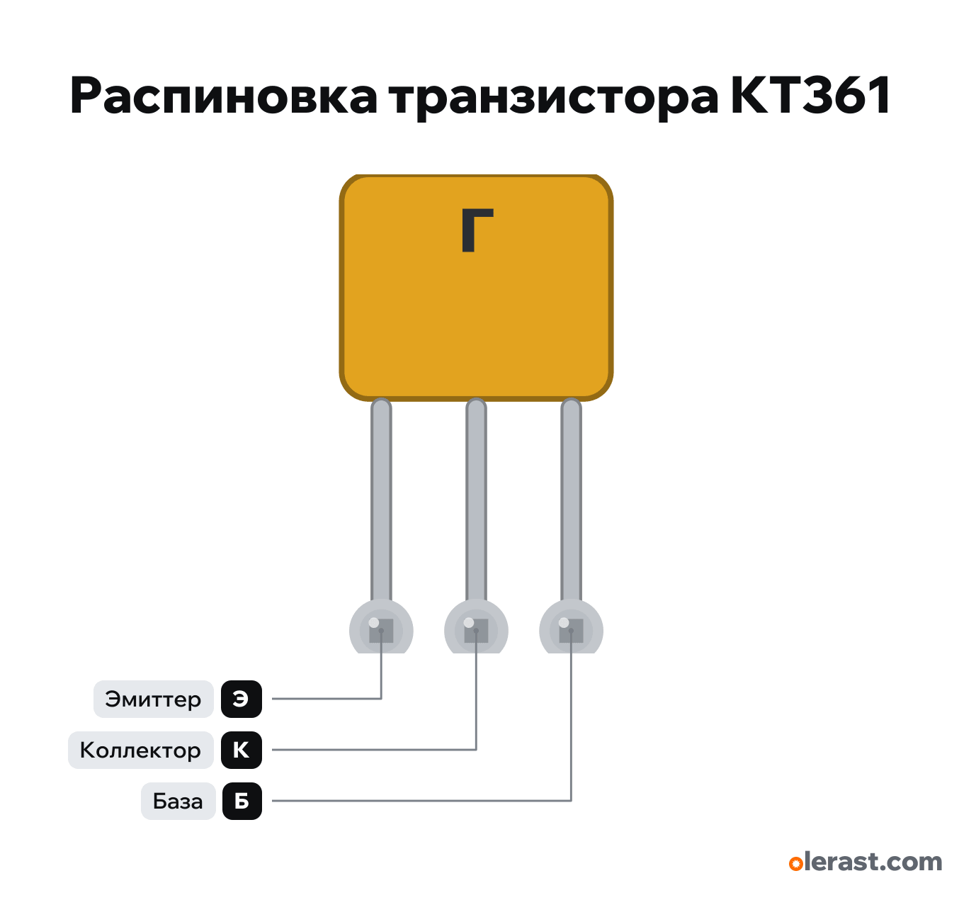
KT361 transistor pinout
KT361 transistor (PNP, KT-13 package), KT361, 5 V logic, 7.6×12.8 mm, 3 pins
partly verified20.10.2026
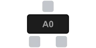
View of the flat side with the letter, pins down: E, C, B from left to right.
Download PNG- Chip
- KT361
- Logic
- 5 V
Important
- High-side switch (PNP): E to positive, load between C and ground, B through 1-4.7 kΩ to GPIO. LOW on the GPIO turns it on, HIGH turns it off.
- The emitter must be at the same voltage as the logic: from an ESP32 only for a 3.3 V load. If the emitter is at 5 V, a 3.3 V HIGH won't turn the transistor off: use an NPN (KT315) on the low side, pulling the base to ground.
- Collector current up to 50 mA, Uce depends on the letter: B 20 V, A 25 V, G and E 35 V, V and D 40 V. Power 150 mW without a heatsink.
- NPN complement: KT315 in the same package, its letter is in the upper left corner.
- Multimeter check in diode mode (PNP): negative probe on B, positive on E and then C, both junctions conduct.
Revisions and clones
- KT361 in the KT-26 package (TO-92, KT361-2, KT361G2 and others): different pin order, check the document for this version.
- KT3107: PNP in KT-26, current up to 100 mA, different pin order.
All pins
| Label | Number | Functions | Limits | Check |
|---|---|---|---|---|
| E | Emitter: to the supply positive | not from manufacturerI found no factory document with the KT-13 pinout online: the E-C-B order is from reference sites and matches the KT315 in the same package. Sources give collector current as 50 or 100 mA, the lower value is used here. Check with a multimeter before soldering: the base reads against both other pins.Labelled on other revisions as: E, emitter | ||
| C | Collector: to the positive side of the load | not from manufacturerI found no factory document with the KT-13 pinout online: the E-C-B order is from reference sites and matches the KT315 in the same package. Sources give collector current as 50 or 100 mA, the lower value is used here. Check with a multimeter before soldering: the base reads against both other pins.Labelled on other revisions as: C, collector | ||
| B | Base: through a resistor to GPIO, LOW turns it on | not from manufacturerI found no factory document with the KT-13 pinout online: the E-C-B order is from reference sites and matches the KT315 in the same package. Sources give collector current as 50 or 100 mA, the lower value is used here. Check with a multimeter before soldering: the base reads against both other pins.Labelled on other revisions as: B, base |
Sources
Not verified against the manufacturer: 3 of 3 pins. The pin card says what confirms each one and where sources disagree.
- Katod-Anod.ru: KT361 transistor (KT361A-KT361E)third-party source, checked 20.10.2026from the letter side, pins down, left to right: emitter, collector, base; Uce and Ucb at Rbe 10 kΩ: A 25, B 20, V and D 40, G and E 35 V; Ic 50 mA; Pc 150 mW up to +35 °C; h21e A and D 20-90, B, G, E 50-350, V 40-160; fT from 250 MHz
- RadioLibrary: KT361G transistorthird-party source, checked 20.10.2026PNP; Uce 35 V; Pc 0.15 W; h21e 50-350; fT from 250 MHz; Ic listed as 100 mA (Katod-Anod says 50 mA)
- Wikipedia: KT361third-party source, checked 20.10.2026KT-13 package, later KT-26 (KT361-2, KT361-3); group letter in the middle of the upper part of the flat side; spec KT361-2 ADBK.432140.995TU (Kremniy)
Size: KT-13 package 7.2×3 mm, pin pitch 2.5 mm (drawn at 2.54) (approximate).