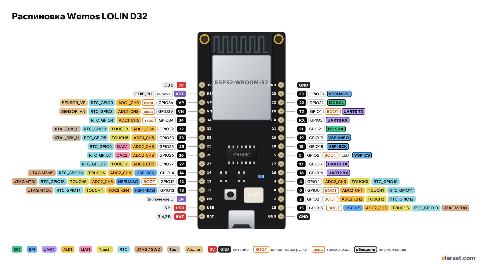
Wemos LOLIN D32 pinout
WEMOS LOLIN D32, ESP32 (ESP32-D0WDQ6), 3.3 V logic, 25.4×57 mm, 32 pins
verified17.10.2026
- 3V3.3 V
- RSTbuttonCHIP_PU
- VPGPIO36inADC1_CH0RTC_GPIO0SENSOR_VP
- VNGPIO39inADC1_CH3RTC_GPIO3SENSOR_VN
- 34GPIO34inADC1_CH6RTC_GPIO4
- 32GPIO32ADC1_CH4TOUCH9RTC_GPIO9XTAL_32K_P
- 33GPIO33ADC1_CH5TOUCH8RTC_GPIO8XTAL_32K_N
- 25GPIO25ADC2_CH8DAC1RTC_GPIO6
- 26GPIO26ADC2_CH9DAC2RTC_GPIO7
- 27GPIO27ADC2_CH7TOUCH7RTC_GPIO17
- 14GPIO14HSPI SCKADC2_CH6TOUCH6RTC_GPIO16JTAG MTMS
- 12GPIO12BOOTHSPI MISOADC2_CH5TOUCH5RTC_GPIO15JTAG MTDI
- 13GPIO13HSPI MOSIADC2_CH4TOUCH4RTC_GPIO14JTAG MTCK
- EN3.3 V regulator enable
- USB5 V
- BAT3-4.2 V
- GND
- 23GPIO23VSPI MOSI
- 22GPIO22I2C SCL
- TXGPIO1BOOTUART0 TX
- RXGPIO3UART0 RX
- 21GPIO21I2C SDA
- 19GPIO19VSPI MISO
- 18GPIO18VSPI SCK
- 5GPIO5BOOTLEDVSPI CS
- 17GPIO17UART2 TX
- 16GPIO16UART2 RX
- 4GPIO4ADC2_CH0TOUCH0RTC_GPIO10
- 0GPIO0BOOTADC2_CH1TOUCH1RTC_GPIO11
- 2GPIO2BOOTADC2_CH2TOUCH2RTC_GPIO12
- 15GPIO15BOOTHSPI CSADC2_CH3TOUCH3RTC_GPIO13JTAG MTDO
- GND
Top view, USB at the bottom, module antenna at the top.
CompareDownload PNG- Chip
- ESP32 (ESP32-D0WDQ6), ESP32-WROOM-32 (4 MB flash)
- Logic
- 3.3 V
- Power
- Micro-USB 4.75-5.25 VLi-ion 3.7 V (PH-2.0 connector) 3.3-4.2 VUSB 4.75-5.25 V3V 3-3.6 V
- Defaults in arduino-esp32 (board "LOLIN D32")
- I2C: SDA 21, SCL 22SPI: MOSI 23, MISO 19, SCK 18, SS 5UART: TX 1, RX 3LED: 5
Which Wemos LOLIN D32 pins are safe to use
Free to use
GPIO3, GPIO4, GPIO13, GPIO14, GPIO16-19, GPIO21-23, GPIO25-27, GPIO32, GPIO33
Use with care
- GPIO0, GPIO2, GPIO5, GPIO12, GPIO15: strapping: the level at power-up selects the boot mode.
- GPIO1: signal at boot.
- GPIO34, GPIO36, GPIO39: input only, no output and no pull-ups.
Important
- 3.3 V logic, don't put 5 V on the GPIO.
- 34, 35, 36 (VP), 39 (VN) are input only, no pull-ups.
- ADC2 (GPIO0, 2, 4, 12–15, 25–27) doesn't work with Wi-Fi on. With Wi-Fi, use ADC1: 32–39.
- Battery voltage: GPIO35 through a 100k/100k divider (not broken out to the header): Vbat = analogRead × 2.
- LED on GPIO5 (lights when LOW).
- The EN pin is the regulator enable, not a reset. Reset is RST.
- Strapping: 0, 2, 5, 12, 15. Keep GPIO12 low at power-up.
- Silkscreen labels from the photo, nets from the Wemos schematic; rows are 0.9 inch apart, their position taken from the photo.
- The ME6211 regulator is powered from USB or from the battery (through a P-MOSFET), whichever is higher. The regulator can be turned off with the EN pin.
Revisions and clones
- LOLIN D32 Pro is a different board: WROVER (PSRAM on 16/17), microSD and TFT connector, a different header.
All pins
| Label | Number | Functions | Limits | Check |
|---|---|---|---|---|
| 3V | 3.3 V | power inputpower output | verifiedME6211 regulator output (500 mA) or 3.3 V input. | |
| RST | CHIP_PU: ESP32 enable and reset (low = reset) | onboard pull-uponboard button | verifiedThe schematic net is RESET; there is a RESET button on the board. | |
| VP | GPIO36 | interruptADC1_CH0RTC_GPIO0SENSOR_VP | input onlynot 5 V tolerant | verifiedInput only: no output and no internal pull-ups. |
| VN | GPIO39 | interruptADC1_CH3RTC_GPIO3SENSOR_VN | input onlynot 5 V tolerant | verifiedInput only: no output and no internal pull-ups. |
| 34 | GPIO34 | interruptADC1_CH6RTC_GPIO4 | input onlynot 5 V tolerant | verifiedInput only: no output and no internal pull-ups. |
| 32 | GPIO32 | interruptPWM (LEDC)ADC1_CH4TOUCH9RTC_GPIO9XTAL_32K_P (32 kHz crystal) | not 5 V tolerant | verified |
| 33 | GPIO33 | interruptPWM (LEDC)ADC1_CH5TOUCH8RTC_GPIO8XTAL_32K_N (32 kHz crystal) | not 5 V tolerant | verified |
| 25 | GPIO25 | interruptPWM (LEDC)ADC2_CH8RTC_GPIO6DAC1 | ADC2 doesn't work with Wi-Fi onnot 5 V tolerant | verifiedADC2: while Wi-Fi is running, analogRead on this pin doesn't work. For ADC with Wi-Fi, use ADC1 (GPIO32–39). |
| 26 | GPIO26 | interruptPWM (LEDC)ADC2_CH9RTC_GPIO7DAC2 | ADC2 doesn't work with Wi-Fi onnot 5 V tolerant | verifiedADC2: while Wi-Fi is running, analogRead on this pin doesn't work. For ADC with Wi-Fi, use ADC1 (GPIO32–39). |
| 27 | GPIO27 | interruptPWM (LEDC)ADC2_CH7TOUCH7RTC_GPIO17 | ADC2 doesn't work with Wi-Fi onnot 5 V tolerant | verifiedADC2: while Wi-Fi is running, analogRead on this pin doesn't work. For ADC with Wi-Fi, use ADC1 (GPIO32–39). |
| 14 | GPIO14 | interruptPWM (LEDC)ADC2_CH6TOUCH6RTC_GPIO16HSPI SCKJTAG MTMS | ADC2 doesn't work with Wi-Fi onnot 5 V tolerant | verifiedADC2: while Wi-Fi is running, analogRead on this pin doesn't work. For ADC with Wi-Fi, use ADC1 (GPIO32–39). |
| 12 | GPIO12 | interruptPWM (LEDC)ADC2_CH5TOUCH5RTC_GPIO15HSPI MISOJTAG MTDI | affects boot (strapping)ADC2 doesn't work with Wi-Fi onnot 5 V tolerant | verifiedMTDI: selects the flash voltage at reset. High = 1.8 V, so a module with 3.3 V flash won't boot. Internal pull-down.ADC2: while Wi-Fi is running, analogRead on this pin doesn't work. For ADC with Wi-Fi, use ADC1 (GPIO32–39). |
| 13 | GPIO13 | interruptPWM (LEDC)ADC2_CH4TOUCH4RTC_GPIO14HSPI MOSIJTAG MTCK | ADC2 doesn't work with Wi-Fi onnot 5 V tolerant | verifiedADC2: while Wi-Fi is running, analogRead on this pin doesn't work. For ADC with Wi-Fi, use ADC1 (GPIO32–39). |
| EN | 3.3 V regulator enable (low = off) | onboard pull-up | verifiedThis is not the ESP32 reset but the EN pin of the ME6211 regulator, pulled up to the input through 100 kΩ. Shorting it to GND cuts power to the board. | |
| USB | 5 V | power output | verified5 V from the USB connector (VBUS), present only when USB is connected. | |
| BAT | 3.7 V | power inputpower output | verifiedBattery positive (the same as on the PH-2.0 connector). | |
| GND | Ground | verified | ||
| 23 | GPIO23 | interruptPWM (LEDC)VSPI MOSI | not 5 V tolerant | verified |
| 22 | GPIO22 | interruptPWM (LEDC)I2C SCL | not 5 V tolerant | verified |
| TX | GPIO1 | interruptPWM (LEDC)UART0 TX | outputs a signal at bootnot 5 V tolerant | verifiedPrints the bootloader log at boot (115200 baud).Connected to the CH340C: busy during flashing and Serial. |
| RX | GPIO3 | interruptPWM (LEDC)UART0 RX | not 5 V tolerant | verifiedConnected to the CH340C: busy during flashing and Serial. |
| 21 | GPIO21 | interruptPWM (LEDC)I2C SDA | not 5 V tolerant | verified |
| 19 | GPIO19 | interruptPWM (LEDC)VSPI MISO | not 5 V tolerant | verified |
| 18 | GPIO18 | interruptPWM (LEDC)VSPI SCK | not 5 V tolerant | verified |
| 5 | GPIO5 | interruptPWM (LEDC)VSPI CS (SS) | affects boot (strapping)not 5 V tolerantonboard LED | verifiedStrapping: SDIO slave timing. Internal pull-up, don't pull it low during reset.The on-board LED goes to 3.3 V through 2 kΩ: it lights when LOW. LED_BUILTIN = 5. This is also a strapping pin and SPI SS. |
| 17 | GPIO17 | interruptPWM (LEDC)UART2 TX | not 5 V tolerant | verified |
| 16 | GPIO16 | interruptPWM (LEDC)UART2 RX | not 5 V tolerant | verified |
| 4 | GPIO4 | interruptPWM (LEDC)ADC2_CH0TOUCH0RTC_GPIO10 | ADC2 doesn't work with Wi-Fi onnot 5 V tolerant | verifiedADC2: while Wi-Fi is running, analogRead on this pin doesn't work. For ADC with Wi-Fi, use ADC1 (GPIO32–39). |
| 0 | GPIO0 | interruptPWM (LEDC)ADC2_CH1TOUCH1RTC_GPIO11 | affects boot (strapping)ADC2 doesn't work with Wi-Fi onnot 5 V tolerant | verifiedAt reset: low = firmware download mode (BOOT button). Internal pull-up.ADC2: while Wi-Fi is running, analogRead on this pin doesn't work. For ADC with Wi-Fi, use ADC1 (GPIO32–39).Auto-flashing through the DTR/RTS of the CH340C bridge toggles this pin. |
| 2 | GPIO2 | interruptPWM (LEDC)ADC2_CH2TOUCH2RTC_GPIO12 | affects boot (strapping)ADC2 doesn't work with Wi-Fi onnot 5 V tolerant | verifiedAt reset it must be low or floating for download mode. Internal pull-down.ADC2: while Wi-Fi is running, analogRead on this pin doesn't work. For ADC with Wi-Fi, use ADC1 (GPIO32–39). |
| 15 | GPIO15 | interruptPWM (LEDC)ADC2_CH3TOUCH3RTC_GPIO13HSPI CSJTAG MTDO | affects boot (strapping)ADC2 doesn't work with Wi-Fi onnot 5 V tolerant | verifiedMTDO: low at reset silences the bootloader log on UART0. Internal pull-up.ADC2: while Wi-Fi is running, analogRead on this pin doesn't work. For ADC with Wi-Fi, use ADC1 (GPIO32–39). |
| GND | Ground | verified |
Sources
Every pin is verified against the manufacturer's documents.
- WEMOS: D32 (documentation)user guide, checked 17.10.2026ESP32-WROOM-32, 4 MB, size 57×25.4 mm, LED_BUILTIN GPIO5, analog inputs VP, VN, 32–35, PH-2 2.0 connector, charging up to 500 mA, 3.3 V logic
- WEMOS D32 V1.0.0 schematicschematic, checked 17.10.2026nets JP1 and JP2 (16 + 16): 3V3, RESET, VP, VN, 34, 32, 33, 25, 26, 27, 14, 12, 13, EN, VBUS, VBAT; GND, 23, 22, TXD0, RXD0, 21, 19, 18, 5, 17, 16, 4, 0, 2, 15, GND; ME6211 with EN through 100 kΩ, CH340C, TP4054, 100k/100k divider on IO35, IO5 LED to 3V3 through 2 kΩ
- WEMOS D32 V1.0.0 dimensionsboard drawing, checked 17.10.202657.00×25.40 mm, 2.10 mm holes, 21.40 mm between them
- arduino-esp32: variants/d32/pins_arduino.hArduino core, checked 17.10.2026LED_BUILTIN 5, battery voltage on GPIO35 (BAT_VOLT_PIN)
- ESP32 Series Datasheet (Espressif)datasheet, checked 15.10.2026IO MUX and pin functions, ADC1/ADC2, touch, DAC, RTC GPIO, strapping (GPIO0, 2, 5, 12, 15), flash pins GPIO6–11, input-only GPIO34–39
- ESP-IDF: GPIO & RTC GPIO (ESP32)user guide, checked 15.10.2026GPIO6–11 used by flash, GPIO34–39 input only with no pull-ups, strapping pins, GPIO1/3 UART0
- ESP-IDF: ADC Oneshot Mode Driver (ESP32)user guide, checked 15.10.2026ADC2 can't be used while Wi-Fi is running
- arduino-esp32: variants/esp32/pins_arduino.hArduino core, checked 15.10.2026defaults: TX 1, RX 3, SDA 21, SCL 22, SS 5, MOSI 23, MISO 19, SCK 18
Size: from the Wemos dimension drawing (57×25.4 mm, 2.1 mm holes 21.4 mm apart); row positions from the photo.
FAQ
- Which Wemos LOLIN D32 pins are I2C, SPI and UART?
- By default in arduino-esp32 (board "LOLIN D32"): I2C: SDA GPIO21, SCL GPIO22; SPI: MOSI GPIO23, MISO GPIO19, SCK GPIO18, SS GPIO5; UART: TX GPIO1, RX GPIO3.
- Which pin is the Wemos LOLIN D32 LED on?
- LED on GPIO5 (lights when LOW).
- Are the Wemos LOLIN D32 pins 5 V tolerant?
- No. The logic is 3.3 V and the pins are not 5 V tolerant: use a divider or a level shifter for 5 V signals.
- Does ADC2 on the Wemos LOLIN D32 work with Wi-Fi on?
- No. ADC2 pins (GPIO0, GPIO2, GPIO4, GPIO12-15, GPIO25-27) can't read analog while Wi-Fi is on. With Wi-Fi, use GPIO32-34, GPIO36, GPIO39 for the ADC.
You might also need
Similar boards
Next
- Emotion keychainmy ESP32 project, prototype
- ESP32 music playermy ESP32 project, prototype
- DITHR//CAMmy ESP32 project, prototype
Need firmware or a device built on ESP32? I'll build it to order