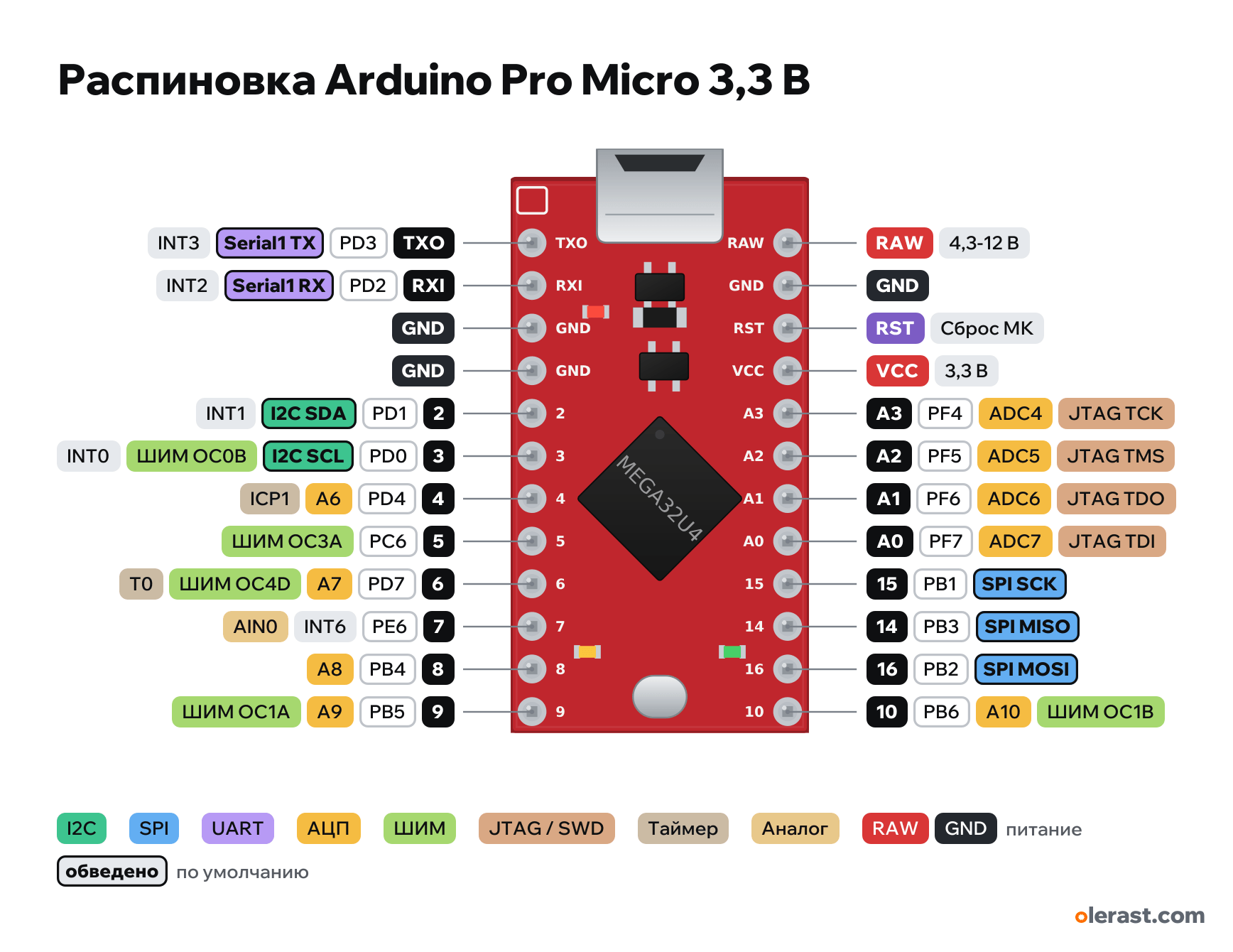
Pro Micro 3.3 V / 8 MHz pinout
Pro Micro 3.3 V / 8 MHz (ATmega32U4), ATmega32U4, 3.3 V logic, 17.78×33.02 mm, 24 pins
verified15.10.2026
Top view, USB at the top.
CompareDownload PNG- Chip
- ATmega32U4
- Logic
- 3.3 V
- Power
- Micro-USB 4.5-5.5 VRAW 4.3-12 VVCC 3.3-3.3 V
- Defaults in Arduino AVR core (SparkFun promicro / leonardo)
- I2C: SDA 2, SCL 3SPI: MOSI 16, MISO 14, SCK 15, SS 17UART: TX 1, RX 0
Which Pro Micro 3.3 V / 8 MHz pins are safe to use
Free to use
D0-D10, D14-D16, A0-A3
Important
- 3.3 V / 8 MHz version: 3.3 V logic, do not apply 5 V to the pins. In the Arduino IDE you must select the processor "ATmega32U4 (3.3V, 8 MHz)".
- Selecting the wrong frequency (8 MHz instead of 16 or vice versa) makes the board stop appearing on USB. Fix it with a double reset (RST to GND twice) and upload within 8 seconds.
- Serial is USB (CDC). The TXO/RXI pins are a separate hardware Serial1.
- No reset button, LED_BUILTIN (13) is not broken out. The RX (17) and TX (30) LEDs light on LOW.
- PWM: 3, 5, 6, 9, 10. Interrupts: 3 (INT0), 2 (INT1), 0 (INT2), 1 (INT3), 7 (INT6). Analog: A0–A3 and 4, 6, 8, 9, 10 (A6–A10).
- USB in the chip itself: suitable for keyboards, mice and gamepads (Keyboard.h, Mouse.h, QMK).
- From USB, RAW is about 4.8 V (after the diode).
Revisions and clones
- Clones: usually the stock Leonardo bootloader (VID:PID 2341:0036, waits 8 s after every reset); jumper J1 may be elsewhere or missing; often 5 V / 16 MHz only.
- SparkFun v20 (Qwiic Pro Micro, USB-C) has a different layout, with a reset button and a Qwiic connector.
- Pro Micro RP2040 and nice!nano are different chips in the same form factor, the pinout differs.
All pins
| Label | Number | Functions | Limits | Check |
|---|---|---|---|---|
| TXO | PD3, Arduino 1 | Serial1 TX (TXD1)INT3 (attachInterrupt 3) | verifiedSerial is USB (CDC), not these pins. The hardware Serial1 is here.Current per pin: up to 20 mA operating, 40 mA limit (datasheet, Absolute Maximum Ratings).Labelled on other revisions as: TX0, TX | |
| RXI | PD2, Arduino 0 | Serial1 RX (RXD1)INT2 (attachInterrupt 2) | verifiedSerial is USB (CDC), not these pins. The hardware Serial1 is here.Current per pin: up to 20 mA operating, 40 mA limit (datasheet, Absolute Maximum Ratings).Labelled on other revisions as: RX1, RX | |
| GND | Ground | verified | ||
| GND | Ground | verified | ||
| 2 | PD1, Arduino 2 | I2C SDAINT1 (attachInterrupt 1) | verifiedCurrent per pin: up to 20 mA operating, 40 mA limit (datasheet, Absolute Maximum Ratings). | |
| 3 | PD0, Arduino 3 | I2C SCLPWM OC0B (Timer0)INT0 (attachInterrupt 0) | verifiedCurrent per pin: up to 20 mA operating, 40 mA limit (datasheet, Absolute Maximum Ratings). | |
| 4 | PD4, Arduino 4 (A6) | A6 (ADC8)ICP1 (Timer1 capture) | verifiedCurrent per pin: up to 20 mA operating, 40 mA limit (datasheet, Absolute Maximum Ratings). | |
| 5 | PC6, Arduino 5 | PWM OC3A (Timer3) | verifiedCurrent per pin: up to 20 mA operating, 40 mA limit (datasheet, Absolute Maximum Ratings). | |
| 6 | PD7, Arduino 6 (A7) | A7 (ADC10)PWM OC4D (Timer4)T0 (Timer0 counter input) | verifiedCurrent per pin: up to 20 mA operating, 40 mA limit (datasheet, Absolute Maximum Ratings). | |
| 7 | PE6, Arduino 7 | INT6 (attachInterrupt 4)AIN0 (comparator +) | verifiedCurrent per pin: up to 20 mA operating, 40 mA limit (datasheet, Absolute Maximum Ratings). | |
| 8 | PB4, Arduino 8 (A8) | A8 (ADC11)PCINT4 | verifiedCurrent per pin: up to 20 mA operating, 40 mA limit (datasheet, Absolute Maximum Ratings). | |
| 9 | PB5, Arduino 9 (A9) | A9 (ADC12)PWM OC1A (Timer1)PCINT5 | verifiedCurrent per pin: up to 20 mA operating, 40 mA limit (datasheet, Absolute Maximum Ratings). | |
| RAW | 12 V | power input | verifiedMIC5219 regulator input. SparkFun: no more than 12 V (their ProMicro.csv table says 5–16 V) and 1 V above VCC. | |
| GND | Ground | verified | ||
| RST | MCU reset (low = reset) | verifiedThere is no reset button on the board. Two quick shorts to GND make the bootloader wait for 8 seconds (this is how you revive a board after a wrong upload). | ||
| VCC | 3.3 V | power inputpower output | verifiedRegulated 3.3 V: regulator output or a supply input that bypasses it. | |
| A3 | PF4, Arduino A3 (21) | ADC4JTAG TCK (if the JTAGEN fuse is enabled) | verifiedCurrent per pin: up to 20 mA operating, 40 mA limit (datasheet, Absolute Maximum Ratings). | |
| A2 | PF5, Arduino A2 (20) | ADC5JTAG TMS (if the JTAGEN fuse is enabled) | verifiedCurrent per pin: up to 20 mA operating, 40 mA limit (datasheet, Absolute Maximum Ratings). | |
| A1 | PF6, Arduino A1 (19) | ADC6JTAG TDO (if the JTAGEN fuse is enabled) | verifiedCurrent per pin: up to 20 mA operating, 40 mA limit (datasheet, Absolute Maximum Ratings). | |
| A0 | PF7, Arduino A0 (18) | ADC7JTAG TDI (if the JTAGEN fuse is enabled) | verifiedCurrent per pin: up to 20 mA operating, 40 mA limit (datasheet, Absolute Maximum Ratings). | |
| 15 | PB1, Arduino 15 | SPI SCKPCINT1 | verifiedCurrent per pin: up to 20 mA operating, 40 mA limit (datasheet, Absolute Maximum Ratings).Labelled on other revisions as: SCK | |
| 14 | PB3, Arduino 14 | SPI MISOPCINT3 | verifiedCurrent per pin: up to 20 mA operating, 40 mA limit (datasheet, Absolute Maximum Ratings).Labelled on other revisions as: MISO | |
| 16 | PB2, Arduino 16 | SPI MOSIPCINT2 | verifiedCurrent per pin: up to 20 mA operating, 40 mA limit (datasheet, Absolute Maximum Ratings).Labelled on other revisions as: MOSI | |
| 10 | PB6, Arduino 10 (A10) | A10 (ADC13)PWM OC1B (Timer1)PCINT6 | verifiedCurrent per pin: up to 20 mA operating, 40 mA limit (datasheet, Absolute Maximum Ratings). |
Sources
Every pin is verified against the manufacturer's documents.
- SparkFun Pro Micro: Hardware/v13/SparkFun_Pro_Micro.brd (GitHub)board drawing, checked 15.10.2026size 17.78×33.02 mm, pad centers of both rows at 12, micro-USB, jumper J1 "Closed for 5V Board", MIC5219, fuse, RX (PB0) and TX (PD5) LEDs with the anode on VCC
- SparkFun: Pro Micro & Fio V3 Hookup Guide — Hardware Overviewuser guide, checked 15.10.2026pin functions, RAW no more than 12 V and 1 V above VCC, interrupts, LED colors
- SparkFun: Pro Micro Hookup Guide — Troubleshooting and FAQuser guide, checked 15.10.2026bootloader 750 ms after reset, 8 s after a double reset; bricking when the wrong board is selected, and recovery
- SparkFun Pro_Micro: Documentation/ProMicro.csvmanufacturer pinout, checked 15.10.2026port, ADC and interrupt of each pin; RAW "5V-16V" (disagrees with the guide)
- SparkFun DEV-12640 Pro Micro 5V/16MHzuser guide, checked 15.10.2026RAW up to 12 V, size 1.3×0.7 inch, fuse and diode on USB
- ATmega16U4/32U4 Datasheet (Microchip DS40002547), sec. 10.3 Alternate Port Functionsdatasheet, checked 15.10.2026alternate functions of ports B, C, D, E, F: OC0B, OC1A/B, OC3A, OC4D, INT0–3, INT6, PCINT0–7 (port B only), SPI on PB1–PB3, TWI on PD0/PD1, USART1 on PD2/PD3, ADC4–7 on PF4–PF7, ADC8 PD4, ADC10 PD7, ADC11–13 PB4–PB6, JTAG on PF4–PF7
- ArduinoCore-avr: variants/leonardo/pins_arduino.hArduino core, checked 15.10.2026Arduino numbers ↔ ATmega32U4 ports, PWM 3, 5, 6, 9, 10 (on Pro Micro), A6–A10 on 4, 6, 8, 9, 10, SDA 2, SCL 3, MISO 14, SCK 15, MOSI 16, SS 17, RX LED 17, TX LED 30
Size: per the SparkFun Eagle file v13 (0.7×1.3 inch); the USB connector protrudes about 1.8 mm.
FAQ
- Which Pro Micro 3.3 V / 8 MHz pins are I2C, SPI and UART?
- By default in Arduino AVR core (SparkFun promicro / leonardo): I2C: SDA D2, SCL D3; SPI: MOSI D16, MISO D14, SCK D15, SS D17; UART: TX D1, RX D0.
- Are the Pro Micro 3.3 V / 8 MHz pins 5 V tolerant?
- No. The logic is 3.3 V and the pins are not 5 V tolerant: use a divider or a level shifter for 5 V signals.
You might also need
Schematic with this board
schematic builder with the board already placed
Flash this board
upload a sketch or .bin to this board from the browser
Power budget
will the regulator cope and how long the battery lasts
Calculators
LED resistor, voltage divider, battery runtime, 3D print cost, LED strip power supply and pF, nF, µF conversion
Similar boards
Next
Need firmware or a device built on Arduino? I'll build it to order