Digispark ATtiny85 pinout
Digispark (ATtiny85, USB-A on the board), ATtiny85, 5 V logic, 26.5×19 mm, 9 pins
verified15.10.2026
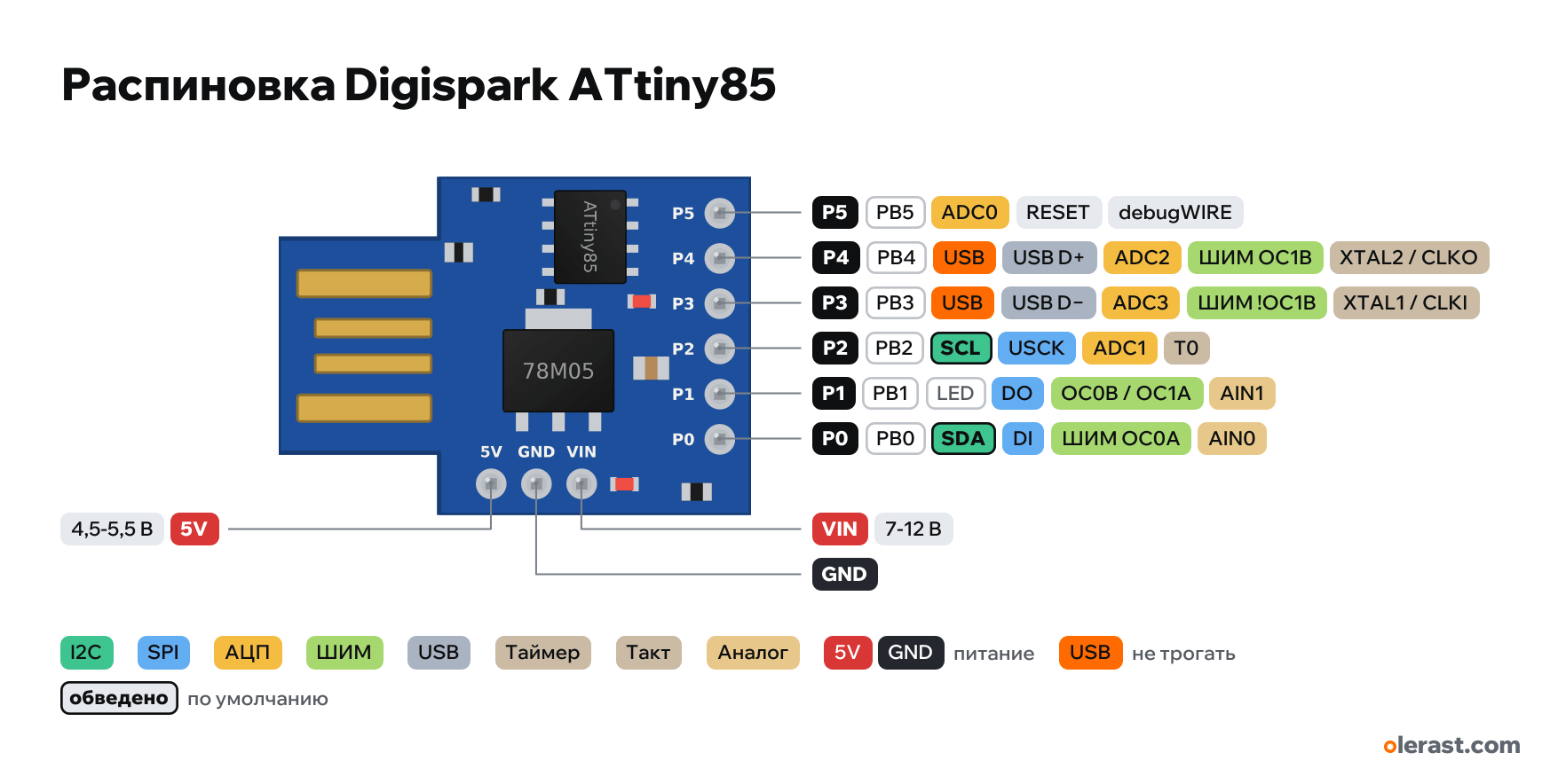
Component side view, USB-A on the left, row P0-P5 on the right, power at the bottom.
CompareDownload PNG- Chip
- ATtiny85
- Logic
- 5 V
- Power
- USB-A (plug into a port) 4.5-5.5 VVIN 7-12 V5V 4.5-5.5 V
Which Digispark ATtiny85 pins are safe to use
Free to use
P0, P2, P5
Use with care
- P1: onboard LED.
- P3, P4: USB lines: use them and you lose USB flashing and the serial port.
Important
- Flashing: click "Upload" first, then plug the board into USB. The micronucleus bootloader waits 5 seconds after power-up, then runs the sketch. Needs the Digistump driver (Windows) and the Digistump AVR board package.
- P3 and P4 are the USB lines (D- and D+): with 3.6 V zeners and a 1.5 kΩ pull-up on P3. Anything connected to them interferes with flashing and distorts the signals.
- LED on P1 (rev2, rev4) or on P0 (unmarked board).
- On clones P5 often stays RESET. On the original it is a weak pin with a high level of about 3 V.
- No hardware UART; I2C and SPI via USI (SDA P0, SCL P2, SCK P2). analogRead numbers: P2 = 1, P4 = 2, P3 = 3, P5 = 0.
- About 6 KB of the 8 KB flash is free, 512 bytes of RAM.
- 78M05 regulator up to 500 mA. ATtiny85 pin current up to 20 mA.
Revisions and clones
- Original Digistump: rev2 and rev4. Digistump never made boards marked "rev3" (clones), functionally the same.
- Clones (usually blue): LED on P0 or P1, RESET fuse not disabled, sometimes a different regulator.
- Digispark Pro (ATtiny167, micro-USB) is a different board with a different pinout.
All pins
| Label | Number | Functions | Limits | Check |
|---|---|---|---|---|
| P5 | PB5, Arduino 5 (A0) | ADC0 (analogRead(0))RESET (until the RSTDISBL fuse is set)debugWIRE (dW)PCINT5 (pin change interrupt) | verifiedCurrent per pin: up to 20 mA operating, 40 mA limit (datasheet, Absolute Maximum Ratings).High level output is about 3 V and weak: not suitable for a load.On the original, RESET is disabled by a fuse and P5 works as a normal pin. On many clones the fuse is untouched: P5 stays RESET and a low level resets the board. It can only be switched with an ISP programmer and reverted only with a high-voltage one. | |
| P4 | PB4, Arduino 4 (A2) | ADC2 (analogRead(2))USB D+ (software V-USB)PWM OC1B (Timer1)XTAL2 / CLKOPCINT4 (pin change interrupt) | USB line | verifiedCurrent per pin: up to 20 mA operating, 40 mA limit (datasheet, Absolute Maximum Ratings).USB D+ line through 66.5 Ω, 3.6 V zener to Ground. If something is connected, the board may not enumerate over USB during flashing. |
| P3 | PB3, Arduino 3 (A3) | ADC3 (analogRead(3))USB D- (software V-USB)PWM !OC1B (inverted)XTAL1 / CLKIPCINT3 (pin change interrupt) | USB lineonboard pull-up | verifiedCurrent per pin: up to 20 mA operating, 40 mA limit (datasheet, Absolute Maximum Ratings).USB D- line through 66.5 Ω, 1.5 kΩ pull-up to 5 V and a 3.6 V zener. Because of the pull-up it reads high as an input. |
| P2 | PB2, Arduino 2 (A1) | ADC1 (analogRead(1))SCL (USI)USCK (USI): SCKINT0T0 (Timer0 counter input)PCINT2 (pin change interrupt) | verifiedCurrent per pin: up to 20 mA operating, 40 mA limit (datasheet, Absolute Maximum Ratings). | |
| P1 | PB1, Arduino 1 | PWM OC0B / OC1ADO (USI): MISO during ISP programming, MOSI in master modeAIN1 (comparator −)PCINT1 (pin change interrupt) | onboard LED | verifiedCurrent per pin: up to 20 mA operating, 40 mA limit (datasheet, Absolute Maximum Ratings).LED on rev2/rev4 and in the board file. On unmarked boards the LED is on P0. |
| P0 | PB0, Arduino 0 | PWM OC0A (Timer0)SDA (USI)DI (USI): MOSI during ISP programming, MISO in master modeAIN0 (comparator +), AREFPCINT0 (pin change interrupt) | verifiedCurrent per pin: up to 20 mA operating, 40 mA limit (datasheet, Absolute Maximum Ratings).On unmarked boards the LED is here: it interferes with I2C, Digistump advises cutting the trace. | |
| 5V | 5 V | power inputpower output | verified78M05 output (or USB) and regulated 5 V input. | |
| GND | Ground | verified | ||
| VIN | 12 V | power input | verified78M05 input: up to 12 V recommended, above that a heatsink is needed (up to 35 V allowed per the product page). |
Sources
Every pin is verified against the manufacturer's documents.
- Digistump: Digispark Eagle (DIGISPARK_PRODUCTION_REV3.brd from the archive 3a5187f5_digispark_sources.zip, copy on GitHub)board drawing, checked 15.10.2026outline 26.5×19.0 mm with the 9.0×12.03 mm USB-A tab, pad centers P0-P5 and 5V/GND/VIN, USB contacts, positions of ATtiny85, 78M05, zeners, resistors, LEDs; nets P0=PB0 ... P5=PB5, LED on P1
- Digistump wiki: Digispark quick reference (archive)user guide, checked 15.10.2026I2C SDA P0, SCL P2; PWM P0, P1, P4; ADC P2-P5 (analogRead numbers), LED depends on revision, VIN 7-12 V, 5V 4.5-5.5 V, 1.5 kΩ pull-up on P3
- Digistump wiki: Digispark pin guide (archive)user guide, checked 15.10.20263.6 V zeners on P3 and P4 (USB lines), PWM frequencies 504 Hz (P0, P1) and 1007 Hz (P4)
- Digistump wiki: identifying the model (archive)user guide, checked 15.10.2026unmarked board: LED on P0, rev2/rev4: on P1; Digistump never made a "rev3" (clones)
- Digistump: Digispark, product page (archive)user guide, checked 15.10.2026powered from USB or 7-35 V (up to 12 V recommended), 5 V 500 mA regulator, about 6 KB of flash free
- Wolles Elektronikkiste: Digispark, the convenient ATtiny85 alternativethird-party source, checked 15.10.2026on clones the RSTDISBL fuse is often not set: P5 stays RESET
- ATtiny25/45/85 Datasheet (Microchip DS40001911), section 10.3 Alternate Port Functionsdatasheet, checked 15.10.2026PB0: MOSI/DI/SDA/AIN0/OC0A/AREF; PB1: MISO/DO/AIN1/OC0B/OC1A; PB2: SCK/USCK/SCL/ADC1/T0/INT0; PB3: XTAL1/CLKI/!OC1B/ADC3; PB4: XTAL2/CLKO/OC1B/ADC2; PB5: RESET/ADC0/dW; PCINT0-5 on all
Size: from the Digistump Eagle file: 26.5×19.0 mm including the USB-A tab (9.0×12.03 mm).
FAQ
- Which pin is the Digispark ATtiny85 LED on?
- LED on P1 (on unmarked boards on P0).
You might also need
Schematic with this board
schematic builder with the board already placed
Flash this board
upload a sketch or .bin to this board from the browser
Power budget
will the regulator cope and how long the battery lasts
Calculators
LED resistor, voltage divider, battery runtime, 3D print cost, LED strip power supply and pF, nF, µF conversion
Similar boards
Next
Need firmware or a device built on Arduino? I'll build it to order