Through-hole resistor 0.25 W pinout
Through-hole resistor 0.25 W (metal film, 1 %), Resistor, 5 V logic, 12.7×4.4 mm, 2 pins
verified17.10.2026
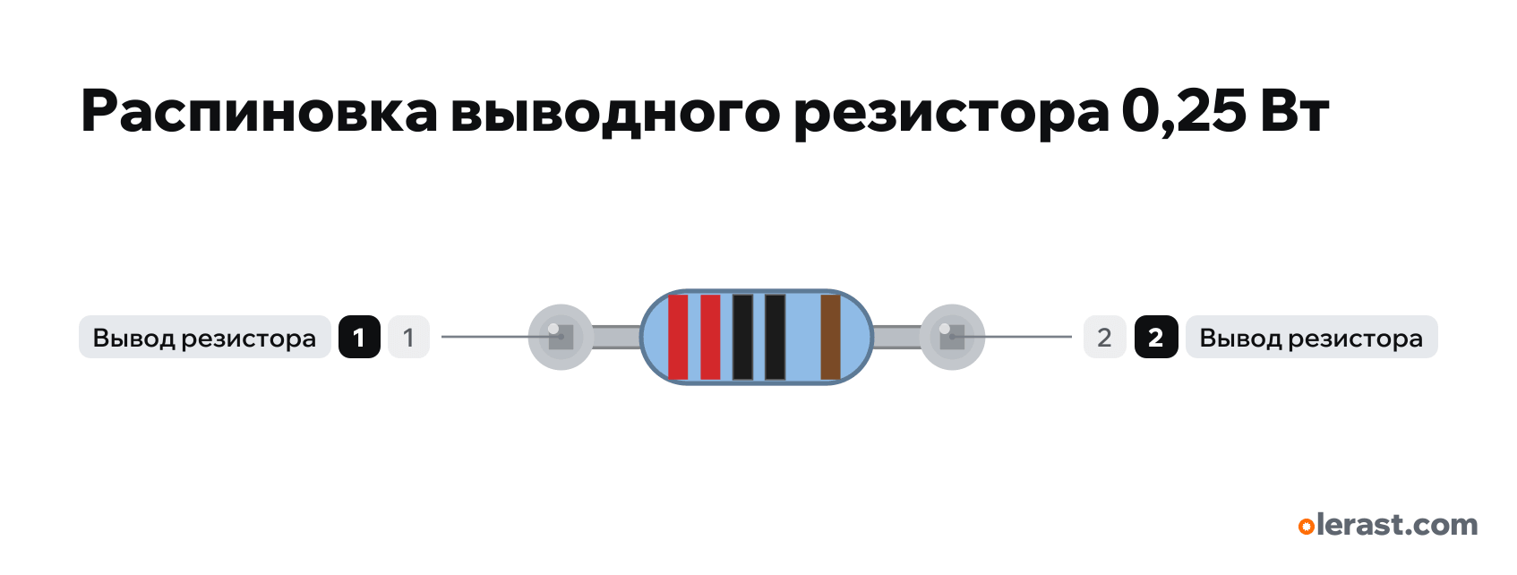
Lying flat, lead 1 on the left; read the bands from the edge they are closer to.
Download PNG- Chip
- Resistor
- Logic
- 5 V
Important
- No polarity: leads 1 and 2 are interchangeable.
- The value and power are set per part in the builder: the bands and the label in the drawing change automatically (as in the /tools/marking decoder).
- Power dissipated in a resistor P = I² × R: a 20 mA LED through 150 Ω is 0.06 W, 0.25 W leaves plenty of margin.
All pins
Sources
Every pin is verified against the manufacturer's documents.
- IEC 60062:2016 Marking codes for resistors and capacitors (color table in /tools/marking)third-party source, checked 17.10.2026band colors: digits, multiplier, tolerance; five bands on 1 % resistors
- Vishay MBA/SMA 0204, MBB/SMA 0207, MBE/SMA 0414 (Document 28766, 11-Jul-2018)datasheet, checked 17.10.2026DIN 0207 body: 6.3×2.5 mm; P70 0.6 W for the MBB 0207; leads have no polarity
Size: body 6.3×2.5 mm (Vishay MBB 0207), 6×2.3 mm for kit resistors; leads bent to 10.16 mm (4 breadboard holes) (approximate).