Seeed XIAO ESP32C6 pinout
Seeed XIAO ESP32C6, ESP32-C6, 3.3 V logic, 17.8×20.975 mm, 14 pins
verified17.10.2026
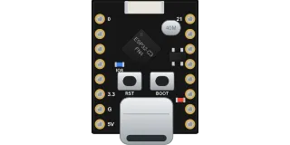
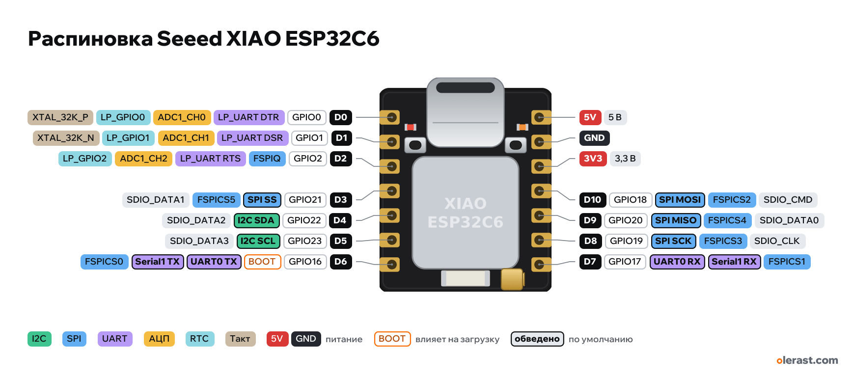
Top view, USB-C at the top.
CompareDownload PNG- Chip
- ESP32-C6, ESP32-C6 + 4 MB flash
- Logic
- 3.3 V
- Power
- USB-C 4.75-5.25 V5V 4.75-5.25 VLi-ion 3.7 V (BAT+ and BAT− pads on the back) 3.3-4.2 V
- Defaults in arduino-esp32 (XIAO_ESP32C6)
- I2C: SDA 22, SCL 23SPI: MOSI 18, MISO 20, SCK 19, SS 21UART: TX 16, RX 17LED: 15
Which Seeed XIAO ESP32C6 pins are safe to use
Free to use
GPIO0-2, GPIO17-23
Use with care
- GPIO16: signal at boot.
Important
- 3.3 V logic, don't put 5 V on the GPIO.
- The labels D0…D10, 5V, GND, 3V3 are printed on the back (the screen is on top), the Arduino numbers are D0…D10, not GPIO.
- Orange LED on GPIO15 (lights when LOW), not broken out to the header.
- Antenna: GPIO3 = LOW enables the RF switch, GPIO14 selects the antenna (LOW for ceramic, HIGH for U.FL).
- No strapping pins on the header; the BOOT button is GPIO9.
- ADC: D0–D2 (ADC1, LP GPIO). Battery voltage can be measured on A0 through a 1:2 divider (200 kΩ).
- JTAG pins (MTMS 4, MTDI 5, MTCK 6, MTDO 7) are broken out as pads on the back.
- Placement of small components is approximate, pins and size follow the Seeed footprint.
All pins
| Label | Number | Functions | Limits | Check |
|---|---|---|---|---|
| D0 | GPIO0, Arduino D0 (0) | interruptPWM (LEDC)ADC1_CH0LP_GPIO0XTAL_32K_PLP_UART DTR | not 5 V tolerant | verified |
| D1 | GPIO1, Arduino D1 (1) | interruptPWM (LEDC)ADC1_CH1LP_GPIO1XTAL_32K_NLP_UART DSR | not 5 V tolerant | verified |
| D2 | GPIO2, Arduino D2 (2) | interruptPWM (LEDC)ADC1_CH2LP_GPIO2LP_UART RTSFSPIQ | not 5 V tolerant | verified |
| D3 | GPIO21, Arduino D3 (21) | interruptPWM (LEDC)SDIO_DATA1FSPICS5SPI SS | not 5 V tolerant | verified |
| D4 | GPIO22, Arduino D4 (22) | interruptPWM (LEDC)SDIO_DATA2I2C SDA | not 5 V tolerant | verified |
| D5 | GPIO23, Arduino D5 (23) | interruptPWM (LEDC)SDIO_DATA3I2C SCL | not 5 V tolerant | verified |
| D6 | GPIO16, Arduino D6 (16) | interruptPWM (LEDC)UART0 TXFSPICS0Serial1 TX | outputs a signal at bootnot 5 V tolerant | verified |
| 5V | 5 V | power inputpower output | verified5 V from USB-C (output) or a 5 V input. Nothing here when running from a battery. | |
| GND | Ground | verified | ||
| 3V3 | 3.3 V | power output | verifiedBoard 3.3 V regulator output. | |
| D10 | GPIO18, Arduino D10 (18) | interruptPWM (LEDC)SDIO_CMDFSPICS2SPI MOSI | not 5 V tolerant | verified |
| D9 | GPIO20, Arduino D9 (20) | interruptPWM (LEDC)SDIO_DATA0FSPICS4SPI MISO | not 5 V tolerant | verified |
| D8 | GPIO19, Arduino D8 (19) | interruptPWM (LEDC)SDIO_CLKFSPICS3SPI SCK | not 5 V tolerant | verified |
| D7 | GPIO17, Arduino D7 (17) | interruptPWM (LEDC)UART0 RXFSPICS1Serial1 RX | not 5 V tolerant | verified |
Sources
Every pin is verified against the manufacturer's documents.
- Seeed Studio Wiki: Getting Started with Seeed XIAO ESP32C6user guide, checked 17.10.2026D0–D10 → GPIO0, 1, 2, 21, 22, 23, 16, 17, 19, 20, 18; LED GPIO15; GPIO3 enables the RF switch, GPIO14 selects the antenna; BOOT button (GPIO9); battery divider 1:2; sleep 15 µA; 21×17.8 mm
- Seeed OPL_Kicad_Library: XIAO-ESP32-C6-DIP.kicad_modboard drawing, checked 17.10.202614 pins: two rows 15.24 mm apart, pitch 2.54, outline 20.975×17.8 mm, outermost pin 2.93 mm from the USB edge
- arduino-esp32: variants/XIAO_ESP32C6/pins_arduino.hArduino core, checked 17.10.2026D0–D10, LED_BUILTIN 15, TX 16, RX 17, SDA 22, SCL 23, SS 21, MOSI 18, MISO 20, SCK 19, WIFI_ENABLE 3, WIFI_ANT_CONFIG 14
- ESP32-C6 Series Datasheet (Espressif)datasheet, checked 17.10.2026pin functions: ADC1_CH0–6 on GPIO0–6, LP GPIO0–7, LP_UART and LP_I2C, USB GPIO12/13, UART0 GPIO16/17, JTAG GPIO4–7, SDIO GPIO18–23, flash GPIO24–30
- ESP-IDF: GPIO (ESP32-C6)user guide, checked 17.10.2026strapping GPIO4, 5, 8, 9, 15; flash GPIO24–30; USB-JTAG GPIO12/13; LP GPIO0–7; ADC1_CH0–6 on GPIO0–6
- arduino-esp32: variants/esp32c6/pins_arduino.hArduino core, checked 17.10.2026defaults: TX 16, RX 17, SDA 23, SCL 22, SS 18, MOSI 19, MISO 20, SCK 21, RGB LED 8
Size: per the Seeed KiCad footprint (21×17.8 mm).
FAQ
- Which Seeed XIAO ESP32C6 pins are I2C, SPI and UART?
- By default in arduino-esp32 (XIAO_ESP32C6): I2C: SDA GPIO22, SCL GPIO23; SPI: MOSI GPIO18, MISO GPIO20, SCK GPIO19, SS GPIO21; UART: TX GPIO16, RX GPIO17.
- Which pin is the Seeed XIAO ESP32C6 LED on?
- Orange LED on GPIO15 (lights when LOW).
- Are the Seeed XIAO ESP32C6 pins 5 V tolerant?
- No. The logic is 3.3 V and the pins are not 5 V tolerant: use a divider or a level shifter for 5 V signals.
You might also need
Schematic with this board
schematic builder with the board already placed
Flash this board
upload a sketch or .bin to this board from the browser
Power budget
will the regulator cope and how long the battery lasts
Calculators
LED resistor, voltage divider, battery runtime, 3D print cost, LED strip power supply and pF, nF, µF conversion
Similar boards
Next
- Emotion keychainmy ESP32-C5 project, prototype
- ESP32 music playermy ESP32 project, prototype
- DITHR//CAMmy ESP32 project, prototype
Need firmware or a device built on ESP32? I'll build it to order