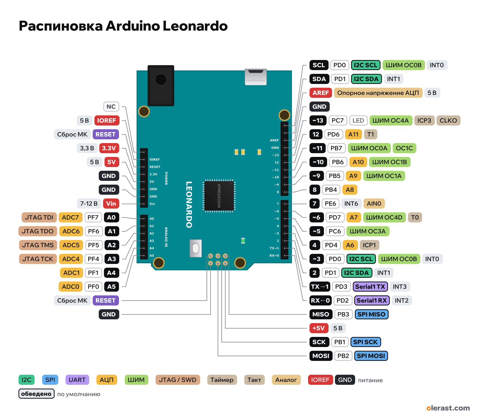
Arduino Leonardo pinout
Arduino Leonardo (ATmega32U4), ATmega32U4, 5 V logic, 68.58×53.34 mm, 38 pins
verified17.10.2026
- NC
- IOREF5 V
- RESETMCU reset
- 3.3V3.3 V
- 5V5 V
- GND
- GND
- Vin7-12 V
- A0PF718ADC7JTAG TDI
- A1PF619ADC6JTAG TDO
- A2PF520ADC5JTAG TMS
- A3PF421ADC4JTAG TCK
- A4PF122ADC1
- A5PF023ADC0
- RESETMCU reset
- GND
- SCLPD03I2C SCLPWM OC0BINT0
- SDAPD12I2C SDAINT1
- AREFADC reference voltage5 V
- GND
- ~13PC713LEDPWM OC4AICP3CLKO
- 12PD6A11T1
- ~11PB711PWM OC0AOC1C
- ~10PB610A10PWM OC1B
- ~9PB59A9PWM OC1A
- 8PB4A8
- 7PE6INT6AIN0
- ~6PD76A7PWM OC4DT0
- ~5PC65PWM OC3A
- 4PD4A6ICP1
- ~3PD03I2C SCLPWM OC0BINT0
- 2PD1I2C SDAINT1
- TX→1PD31Serial1 TXINT3
- RX←0PD20Serial1 RXINT2
- MISOPB3SPI MISO
- +5V5 V
- SCKPB1SPI SCK
- MOSIPB2SPI MOSI
Top view, USB and DC jack on the left, rotated 90° on the diagram.
CompareDownload PNG- Chip
- ATmega32U4
- Logic
- 5 V
- Power
- Micro-USB 4.75-5.25 VVIN / DC jack 7-12 V5V
- Defaults in Arduino AVR core (Leonardo)
- I2C: SDA 2, SCL 3SPI: MOSI 16, MISO 14, SCK 15, SS 17UART: TX 1, RX 0LED: 13
Which Arduino Leonardo pins are safe to use
Free to use
D0-D12, A0-A5, MISO, MOSI, SCK
Use with care
- D13: onboard LED.
Important
- 5 V logic.
- Serial is USB; D0/D1 are a separate hardware Serial1.
- I2C is on D2 (SDA) and D3 (SCL), not on A4/A5 as on the Uno: shields that take I2C from A4/A5 don't work without jumper wires.
- SPI is only on the ICSP connector (D14–D16), not on D11–D13.
- attachInterrupt interrupts: 0, 1, 2, 3, 7. PWM: 3, 5, 6, 9, 10, 11, 13.
- D4, D6, D8, D9, D10, D12 are also analog inputs A6–A11.
- The board shows up on the computer as a keyboard or mouse (Keyboard.h, Mouse.h). If it hangs: double-press RESET and flash right away.
All pins
| Label | Number | Functions | Limits | Check |
|---|---|---|---|---|
| SCL | PD0, Arduino 3 | I2C SCLPWM OC0B (Timer0)INT0 (attachInterrupt 0) | verifiedCurrent per pin: up to 20 mA operating, 40 mA limit (datasheet, Absolute Maximum Ratings).Separate I2C SCL pin, connected to D3 (not to A5 as on the Uno). | |
| SDA | PD1, Arduino 2 | I2C SDAINT1 (attachInterrupt 1) | verifiedCurrent per pin: up to 20 mA operating, 40 mA limit (datasheet, Absolute Maximum Ratings).Separate I2C SDA pin, connected to D2 (not to A4 as on the Uno). | |
| AREF | 5 VADC reference voltage | power input | verifiedExternal reference for analogRead. No higher than 5 V. | |
| GND | Ground | verified | ||
| ~13 | PC7, Arduino 13 | PWM OC4A (Timer4)ICP3 (Timer3 capture)CLKO | onboard LED | verifiedCurrent per pin: up to 20 mA operating, 40 mA limit (datasheet, Absolute Maximum Ratings).L LED on the board. LED_BUILTIN = 13. |
| 12 | PD6, Arduino 12 | A11 (ADC9)T1 (Timer1 counter input) | verifiedCurrent per pin: up to 20 mA operating, 40 mA limit (datasheet, Absolute Maximum Ratings). | |
| ~11 | PB7, Arduino 11 | PWM OC0A (Timer0)OC1C (Timer1)PCINT7 | verifiedCurrent per pin: up to 20 mA operating, 40 mA limit (datasheet, Absolute Maximum Ratings). | |
| ~10 | PB6, Arduino 10 | A10 (ADC13)PWM OC1B (Timer1)PCINT6 | verifiedCurrent per pin: up to 20 mA operating, 40 mA limit (datasheet, Absolute Maximum Ratings). | |
| ~9 | PB5, Arduino 9 | A9 (ADC12)PWM OC1A (Timer1)PCINT5 | verifiedCurrent per pin: up to 20 mA operating, 40 mA limit (datasheet, Absolute Maximum Ratings). | |
| 8 | PB4, Arduino 8 | A8 (ADC11)PCINT4 | verifiedCurrent per pin: up to 20 mA operating, 40 mA limit (datasheet, Absolute Maximum Ratings). | |
| 7 | PE6, Arduino 7 | INT6 (attachInterrupt 4)AIN0 (comparator +) | verifiedCurrent per pin: up to 20 mA operating, 40 mA limit (datasheet, Absolute Maximum Ratings). | |
| ~6 | PD7, Arduino 6 | A7 (ADC10)PWM OC4D (Timer4)T0 (Timer0 counter input) | verifiedCurrent per pin: up to 20 mA operating, 40 mA limit (datasheet, Absolute Maximum Ratings). | |
| ~5 | PC6, Arduino 5 | PWM OC3A (Timer3) | verifiedCurrent per pin: up to 20 mA operating, 40 mA limit (datasheet, Absolute Maximum Ratings). | |
| 4 | PD4, Arduino 4 | A6 (ADC8)ICP1 (Timer1 capture) | verifiedCurrent per pin: up to 20 mA operating, 40 mA limit (datasheet, Absolute Maximum Ratings). | |
| ~3 | PD0, Arduino 3 | I2C SCLPWM OC0B (Timer0)INT0 (attachInterrupt 0) | verifiedCurrent per pin: up to 20 mA operating, 40 mA limit (datasheet, Absolute Maximum Ratings). | |
| 2 | PD1, Arduino 2 | I2C SDAINT1 (attachInterrupt 1) | verifiedCurrent per pin: up to 20 mA operating, 40 mA limit (datasheet, Absolute Maximum Ratings). | |
| TX→1 | PD3, Arduino 1 | Serial1 TX (TXD1)INT3 (attachInterrupt 3) | verifiedSerial is USB (CDC), not these pins. The hardware Serial1 is here.Current per pin: up to 20 mA operating, 40 mA limit (datasheet, Absolute Maximum Ratings). | |
| RX←0 | PD2, Arduino 0 | Serial1 RX (RXD1)INT2 (attachInterrupt 2) | verifiedSerial is USB (CDC), not these pins. The hardware Serial1 is here.Current per pin: up to 20 mA operating, 40 mA limit (datasheet, Absolute Maximum Ratings). | |
| - | not connected | verifiedNot connected (reserved). | ||
| IOREF | 5 V | power output | verifiedBoard logic voltage (5 V) for shields. | |
| RESET | MCU reset (low = reset) | verified | ||
| 3.3V | 3.3 V | power output | verified3.3 V regulator, up to 50 mA (Leonardo specifications). | |
| 5V | 5 V | power inputpower output | verified | |
| GND | Ground | verified | ||
| GND | Ground | verified | ||
| Vin | 9 V | power input | verified5 V regulator input: 7–12 V, limit 6–20 V. | |
| A0 | PF7, Arduino A0 (18) | ADC7JTAG TDI (if the JTAGEN fuse is enabled) | verifiedCurrent per pin: up to 20 mA operating, 40 mA limit (datasheet, Absolute Maximum Ratings). | |
| A1 | PF6, Arduino A1 (19) | ADC6JTAG TDO (if the JTAGEN fuse is enabled) | verifiedCurrent per pin: up to 20 mA operating, 40 mA limit (datasheet, Absolute Maximum Ratings). | |
| A2 | PF5, Arduino A2 (20) | ADC5JTAG TMS (if the JTAGEN fuse is enabled) | verifiedCurrent per pin: up to 20 mA operating, 40 mA limit (datasheet, Absolute Maximum Ratings). | |
| A3 | PF4, Arduino A3 (21) | ADC4JTAG TCK (if the JTAGEN fuse is enabled) | verifiedCurrent per pin: up to 20 mA operating, 40 mA limit (datasheet, Absolute Maximum Ratings). | |
| A4 | PF1, Arduino A4 (22) | ADC1 | verifiedCurrent per pin: up to 20 mA operating, 40 mA limit (datasheet, Absolute Maximum Ratings). | |
| A5 | PF0, Arduino A5 (23) | ADC0 | verifiedCurrent per pin: up to 20 mA operating, 40 mA limit (datasheet, Absolute Maximum Ratings). | |
| MISO | PB3 | SPI MISOPCINT3 | verifiedCurrent per pin: up to 20 mA operating, 40 mA limit (datasheet, Absolute Maximum Ratings).Same signal as D14. | |
| +5V | 5 V | power inputpower output | verified | |
| SCK | PB1 | SPI SCKPCINT1 | verifiedCurrent per pin: up to 20 mA operating, 40 mA limit (datasheet, Absolute Maximum Ratings).Same signal as D15. | |
| MOSI | PB2 | SPI MOSIPCINT2 | verifiedCurrent per pin: up to 20 mA operating, 40 mA limit (datasheet, Absolute Maximum Ratings).Same signal as D16. | |
| RESET | MCU reset (low = reset) | verified | ||
| GND | Ground | verified |
Sources
Every pin is verified against the manufacturer's documents.
- Arduino Leonardo Datasheet (A000057)datasheet, checked 17.10.2026connectors as on the Uno, SDA/SCL next to AREF on D2/D3, SPI only on ICSP, PWM 3, 5, 6, 9, 10, 11, 13, interrupts 0, 1, 2, 3, 7, 3.3 V 50 mA
- Arduino UNO R3: Eagle files UNO-TH_Rev3e (Uno outline and connectors, shared by boards of this size)board drawing, checked 17.10.2026size 68.58×53.34 mm, connector pad centers, ICSP and holes are the same on boards in the Uno form factor
- ATmega16U4/32U4 Datasheet (Microchip DS40002547), sec. 10.3 Alternate Port Functionsdatasheet, checked 15.10.2026alternate functions of ports B, C, D, E, F: OC0B, OC1A/B, OC3A, OC4D, INT0–3, INT6, PCINT0–7 (port B only), SPI on PB1–PB3, TWI on PD0/PD1, USART1 on PD2/PD3, ADC4–7 on PF4–PF7, ADC8 PD4, ADC10 PD7, ADC11–13 PB4–PB6, JTAG on PF4–PF7
- ArduinoCore-avr: variants/leonardo/pins_arduino.hArduino core, checked 15.10.2026Arduino numbers ↔ ATmega32U4 ports, PWM 3, 5, 6, 9, 10 (on Pro Micro), A6–A10 on 4, 6, 8, 9, 10, SDA 2, SCL 3, MISO 14, SCK 15, MOSI 16, SS 17, RX LED 17, TX LED 30
Size: size and connectors as on the Uno R3; components approximate.
FAQ
- Which Arduino Leonardo pins are I2C, SPI and UART?
- By default in Arduino AVR core (Leonardo): I2C: SDA D2, SCL D3; SPI: MOSI D16, MISO D14, SCK D15, SS D17; UART: TX D1, RX D0.
- Which pin is the Arduino Leonardo LED on?
- L LED on D13.
You might also need
Schematic with this board
schematic builder with the board already placed
Flash this board
upload a sketch or .bin to this board from the browser
Power budget
will the regulator cope and how long the battery lasts
Calculators
LED resistor, voltage divider, battery runtime, 3D print cost, LED strip power supply and pF, nF, µF conversion
Similar boards
Next
Need firmware or a device built on Arduino? I'll build it to order