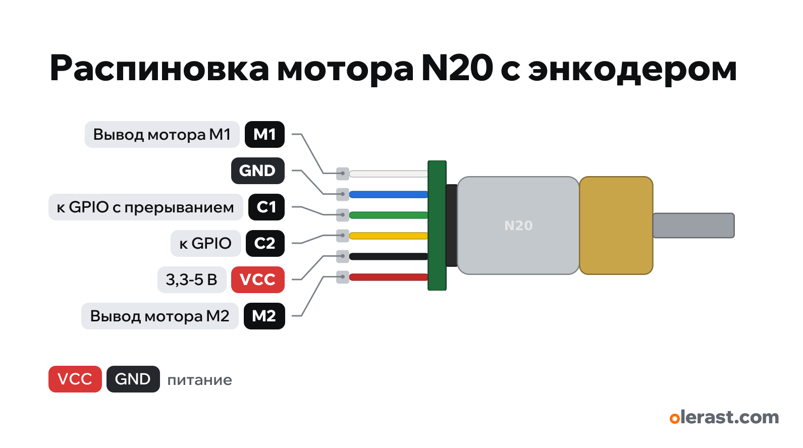
N20 gear motor with Hall encoder pinout
N20 gear motor with Hall encoder, 6 pins, brushed motor with gearbox and magnetic encoder, 5 V logic, 50×16 mm, 6 pins
partly verified17.10.2026
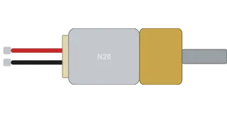
Side view, wires on the left, shaft on the right.
Download PNG- Chip
- brushed motor with gearbox and magnetic encoder
- Logic
- 5 V
- Power
- Encoder VCC 3.3-5 VM1 and M2 through a driver
Important
- Encoder: C1 and C2 are offset by a quarter period. Pulses per output shaft revolution: 7 × gear ratio (×4 when counting all edges of both channels).
- M1 and M2 go to the motor driver, encoder VCC and GND to the board supply, C1 to an interrupt-capable pin.
- The connector on the encoder board is PH2.0 or ZH1.5 (6 pins): get a mating cable for yours.
All pins
| Label | Number | Functions | Limits | Check |
|---|---|---|---|---|
| M1 | Motor pin M1: to the driver output | not verifiedLabels M1, GND, C1, C2, VCC, M2 from seller descriptions; the connector order follows the common encoder board, not checked against a labeled photo. Wire colors differ between sellers (Adafruit motor: white and red).Connect the motor only through a driver (DRV8833, TB6612, L298N) or a transistor with a diode: a GPIO gives up to 20 mA.Swapping M1 and M2 reverses the motor direction.Labelled on other revisions as: white (Adafruit) | ||
| GND | Ground | not verifiedLabels M1, GND, C1, C2, VCC, M2 from seller descriptions; the connector order follows the common encoder board, not checked against a labeled photo. Wire colors differ between sellers (Adafruit motor: white and red).Encoder ground: connect to the board GND. | ||
| C1 | Encoder channel A (Hall sensor) | not verifiedLabels M1, GND, C1, C2, VCC, M2 from seller descriptions; the connector order follows the common encoder board, not checked against a labeled photo. Wire colors differ between sellers (Adafruit motor: white and red).The output level equals the encoder supply: for ESP32 and Pico power the encoder from 3.3 V.Labelled on other revisions as: A | ||
| C2 | Encoder channel B (Hall sensor) | not verifiedLabels M1, GND, C1, C2, VCC, M2 from seller descriptions; the connector order follows the common encoder board, not checked against a labeled photo. Wire colors differ between sellers (Adafruit motor: white and red).Labelled on other revisions as: B | ||
| VCC | 5 V | power input | not verifiedLabels M1, GND, C1, C2, VCC, M2 from seller descriptions; the connector order follows the common encoder board, not checked against a labeled photo. Wire colors differ between sellers (Adafruit motor: white and red).Encoder supply 3.3-5 V. The motor is not powered from this pin. | |
| M2 | Motor pin M2: to the driver output | not verifiedLabels M1, GND, C1, C2, VCC, M2 from seller descriptions; the connector order follows the common encoder board, not checked against a labeled photo. Wire colors differ between sellers (Adafruit motor: white and red).Connect the motor only through a driver (DRV8833, TB6612, L298N) or a transistor with a diode: a GPIO gives up to 20 mA.Swapping M1 and M2 reverses the motor direction.Labelled on other revisions as: red (Adafruit) |
Sources
Not verified against the manufacturer: 6 of 6 pins. The pin card says what confirms each one and where sources disagree.
- Pololu: micro metal gearmotor (N20 format), dimensionsthird-party source, checked 17.10.2026body 12×10 mm, gearbox 9 mm, motor 15 mm, shaft Ø3 with a flat
- Adafruit: N20 DC Motor with Magnetic Encoder - 6V 1:50 (4638)third-party source, checked 17.10.2026motor supply 4.5–6 V, about 100 mA, 200 mA stalled; encoder 3–5 V, two Hall outputs; wire colors
- Probots: GA12-N20 6V micro DC motor with encoderthird-party source, checked 17.10.2026labels M1, M2 (motor), C1, C2 (encoder outputs), VCC, GND; encoder 7 pulses per revolution
Size: motor, gearbox and shaft per Pololu; encoder and wires are schematic (approximate).
FAQ
- What supply voltage does the N20 gear motor with Hall encoder need?
- Encoder VCC: 3.3-5 V.