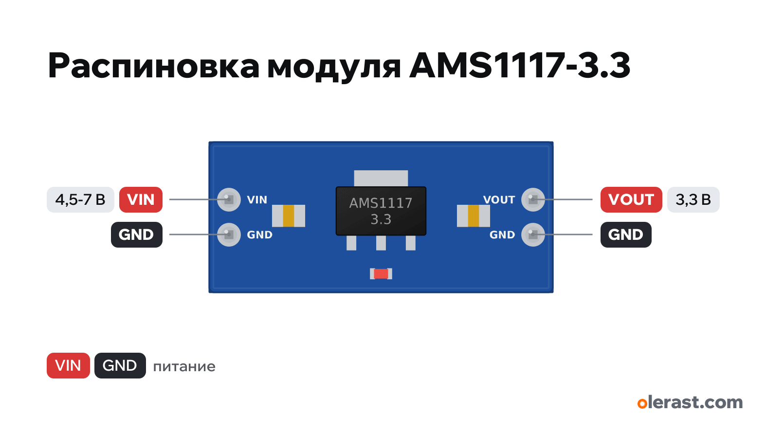
AMS1117-3.3 regulator pinout
AMS1117-3.3 regulator (blue 25×11 module, 4 pins), AMS1117-3.3, 3.3 V logic, 25×11 mm, 4 pins
partly verified15.10.2026
Top view, input on the left, output on the right.
BuyDownload PNG- Chip
- AMS1117-3.3
- Logic
- 3.3 V
- Power
- VIN 4.5-7 V
Important
- Input 4.5–7 V (5 V is best), output 3.3 V. The bigger the difference, the lower the current: at 12 V input, about 75 mA.
- The blue 25×11 mm module with two pins on each end is shown: it is the one most often sold as the "AMS1117-3.3 module". There is also a small 13×9 mm one with three pins (VIN, OUT, GND at ProtoSupplies, other sellers use a different order).
- Read the labels by the pins before connecting: which of the pair is VIN and which is GND is not shown in the sources.
- Boards often carry AMS1117 clones (other manufacturers): quiescent current and dropout can be worse.
- Geometry from third-party KiCad footprints and seller descriptions (±0.5 mm), small components are drawn approximately. Check with calipers before laying out your own board.
- Dropout 1.1 V typ., 1.3 V max: the input needs at least 4.5 V. You can't get 3.3 V from a 3.7 V lithium cell.
- In practice 500–600 mA without overheating at 5 V input (ProtoSupplies test).
Revisions and clones
- 3-pin 13×9 mm module (right-angle header): VIN, OUT, GND per ProtoSupplies; some sellers use VIN, GND, VOUT.
- AMS1117-5.0 and the adjustable AMS1117-ADJ come in identical modules with a different output: check the marking.
All pins
| Label | Number | Functions | Limits | Check |
|---|---|---|---|---|
| VIN | 5 V | power input | not verifiedNone of the sources I found shows which of the two pins on each side is VIN (VOUT) and which is GND. Check the labels on the board. | |
| GND | Ground | not verifiedNone of the sources I found shows which of the two pins on each side is VIN (VOUT) and which is GND. Check the labels on the board. | ||
| VOUT | 3.3 V | power output | not verifiedNone of the sources I found shows which of the two pins on each side is VIN (VOUT) and which is GND. Check the labels on the board.Labelled on other revisions as: 3.3V, OUT | |
| GND | Ground | not verifiedNone of the sources I found shows which of the two pins on each side is VIN (VOUT) and which is GND. Check the labels on the board. |
Sources
Not verified against the manufacturer: 4 of 4 pins. The pin card says what confirms each one and where sources disagree.
- AMS1117 datasheet (Advanced Monolithic Systems)datasheet, checked 15.10.2026input up to 15 V (abs.), dropout 1.1 V typ. / 1.3 V max up to 0.8 A, 22 µF tantalum needed at the output, SOT-223: 1 GND, 2 VOUT, 3 VIN, heat sink tab on VOUT, 1.2 W, 90 °C/W
- Tinytronics: AMS1117 3.3V voltage regulator modulethird-party source, checked 15.10.202625×11 mm, input and output are pins, labels VIN and VOUT, LED, input 4.5–7 V, 800 mA
- KiCad: AdmondDeng/remote ams1117_module.kicad_modthird-party source, checked 15.10.20262 pins at 2.54 pitch on each end, 22.04 mm between the pairs, outline 26.6×12
- ProtoSupplies: AMS1117 5V to 3.3V step-down module (3-pin)third-party source, checked 15.10.2026heating test: 600 mA at 5 V (105 °C on the heat sink), 200 mA at 9 V, 75 mA at 12 V; 3-pin version 13×9 mm: VIN, OUT, GND
Size: 25×11 mm at Tinytronics; AdmondDeng footprint 26.6×12 (approximate).