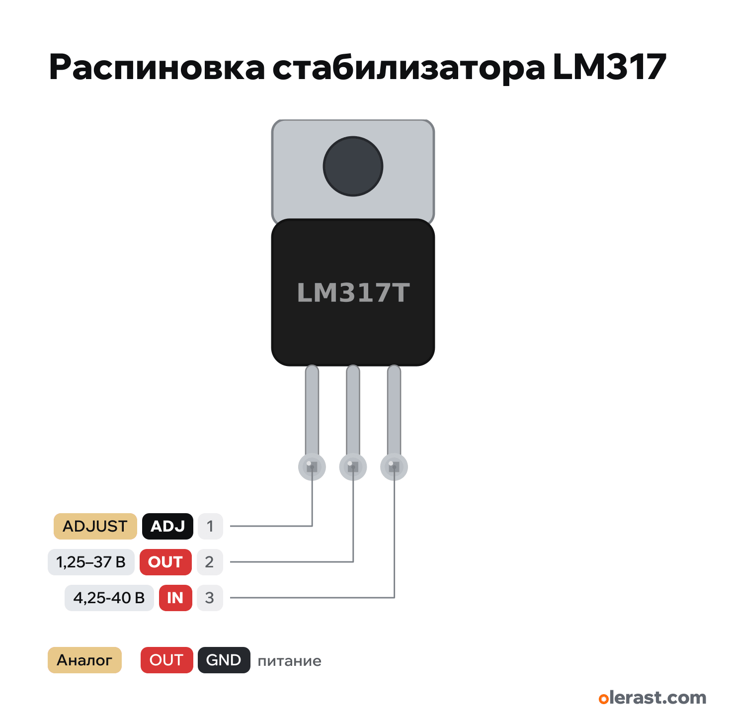
LM317 adjustable regulator pinout
LM317 adjustable regulator (1.25–37 V, TO-220), LM317, 5 V logic, 10.2×23 mm, 3 pins
verified17.10.2026
View of the marking, tab at the top, pins down: 1 on the left.
Download PNG- Chip
- LM317
- Logic
- 5 V
- Power
- IN (pin 3) 4.25-40 V
Important
- Output: Vout = 1.25 × (1 + R2/R1). R1 = 240 Ω between OUT and ADJ, R2 = R1 × (Vout / 1.25 − 1): for 5 V 720 Ω (the nearest 750 Ω gives 5.16 V), for 3.3 V 390 Ω (3.28 V), for 12 V 2.2 kΩ (12.7 V).
- A pair from the E24 series is easy to pick in the divider calculator (/tools/calc/divider, "Pick" mode): input = the Vout you need, output = Vout − 1.25 V, top resistor is R1 (OUT–ADJ), bottom is R2 (ADJ–GND).
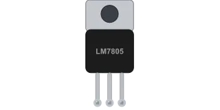
- The pin order differs from the LM7805: ADJ, OUT, IN. The tab is connected to the output.
- In the circuit check the LM317 output is treated as unknown (1.25–37 V): verify the voltage yourself.
- With no load it needs a current of at least 3.5–10 mA: the 240 Ω divider provides it (5 mA).
- The output is set by two resistors: R1 between OUT and ADJ (240 Ω), R2 between ADJ and GND.
All pins
| Label | Number | Functions | Limits | Check |
|---|---|---|---|---|
| ADJ | pin 1 | ADJUST: middle of the R1/R2 divider, 1.25 V below OUT | verifiedTo the middle of the divider: R1 to OUT, R2 to ground. Connected directly to ground, the output is 1.25 V.Labelled on other revisions as: ADJUST, 1 | |
| OUT | pin 2 | 1.25–37 V (set by resistors) | power output | verifiedOutput. The tab is connected to this pin: the heatsink is at the output voltage.Labelled on other revisions as: OUTPUT, VOUT, 2 |
| IN | pin 3 | 12 V | power input | verifiedInput: at least 3 V above the output.Labelled on other revisions as: INPUT, VIN, 3 |
Sources
Every pin is verified against the manufacturer's documents.
- TI LM317 3-Pin Adjustable Regulator datasheet (SLVS044Z, 2025)datasheet, checked 17.10.2026TO-220: 1 ADJUST, 2 OUTPUT (and tab), 3 INPUT; input-output difference 3–40 V, current up to 1.5 A, Vref 1.25 V, R1 240 Ω in the typical circuit
Size: TO-220 package 10×15.2 mm, pins shortened (approximate).