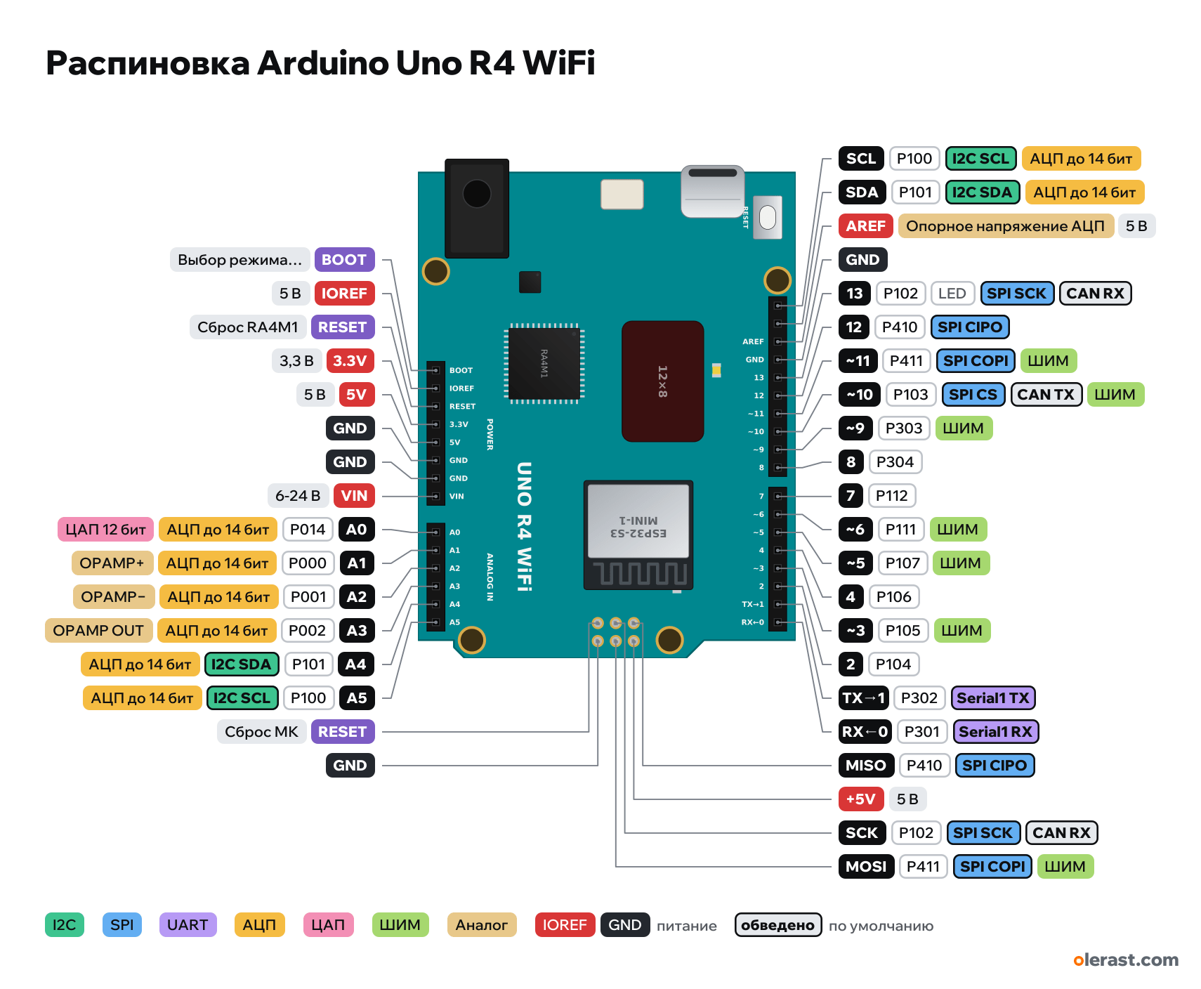
Arduino Uno R4 WiFi pinout
Arduino Uno R4 WiFi, RA4M1, 5 V logic, 68.58×53.34 mm, 38 pins
verified17.10.2026
- BOOTRA4M1 boot mode select
- IOREF5 V
- RESETRA4M1 reset
- 3.3V3.3 V
- 5V5 V
- GND
- GND
- VIN6-24 V
- A0P01414ADC up to 14 bit12-bit DAC
- A1P00015ADC up to 14 bitOPAMP+
- A2P00116ADC up to 14 bitOPAMP−
- A3P00217ADC up to 14 bitOPAMP OUT
- A4P10118I2C SDAADC up to 14 bit
- A5P10019I2C SCLADC up to 14 bit
- RESETMCU reset
- GND
- SCLP100I2C SCLADC up to 14 bit
- SDAP101I2C SDAADC up to 14 bit
- AREFADC reference voltage5 V
- GND
- 13P102LEDSPI SCKCAN RX
- 12P410SPI CIPO
- ~11P41111SPI COPIPWM
- ~10P10310SPI CSCAN TXPWM
- ~9P3039PWM
- 8P304
- 7P112
- ~6P1116PWM
- ~5P1075PWM
- 4P106
- ~3P1053PWM
- 2P104
- TX→1P3021Serial1 TX
- RX←0P3010Serial1 RX
- MISOP410SPI CIPO
- +5V5 V
- SCKP102SPI SCKCAN RX
- MOSIP411SPI COPIPWM
Top view, USB and DC jack on the left (as on the official pinout), rotated 90° on the diagram.
CompareDownload PNG- Chip
- RA4M1
- Logic
- 5 V
- Power
- USB-C 4.75-5.25 VVIN / DC jack 6-24 V5V
- Defaults in ArduinoCore-renesas
- I2C: SDA 18, SCL 19SPI: MOSI 11, MISO 12, SCK 13, SS 10UART: TX 1, RX 0LED: 13
Which Arduino Uno R4 WiFi pins are safe to use
Free to use
D0-D12, A0-A5
Use with care
- D13: onboard LED.
Important
- 5 V logic like the Uno R3; Uno shields are connector-compatible.
- Current per pin is only 8 mA (20 mA on the Uno R3): LEDs only through a resistor of 470 Ω or more, relays and motors only through a transistor.
- VIN 6–24 V through a switching regulator (runs cooler than on the Uno R3).
- Serial is USB, D0/D1 are Serial1 (on the Uno R3 they were the same port).
- ADC up to 14 bit (analogReadResolution(14)), A0 is a true 12-bit DAC, A1–A3 are the built-in op-amp.
- CAN: D10 (TX) and D13 (RX), an external transceiver is required.
- Wi-Fi and Bluetooth via the ESP32-S3 (WiFiS3 library). The ESP32-S3 runs at 3.3 V and is not connected directly to the RA4M1 pins.
- The 12×8 matrix (Arduino_LED_Matrix library) uses 11 RA4M1 pins inside the board and does not touch the headers.
- Qwiic is the second I2C (Wire1) at 3.3 V; A4/A5 and SDA/SCL carry Wire at 5 V.
- RA4M1 ports differ between R4 WiFi and R4 Minima: D2 and D3, D4-D7, D10-D13 go to different chip pins.
- The OFF pin (near the Qwiic connector) to GND turns off the 5 V regulator; VRTC is the battery for the RTC.
All pins
| Label | Number | Functions | Limits | Check |
|---|---|---|---|---|
| SCL | P100 | ADC up to 14 bitI2C SCL (Wire) | verifiedCurrent per pin no more than 8 mA (board datasheet, Pin Current), less than the ATmega328P on the Uno R3.Separate I2C SCL pin, connected to A5. | |
| SDA | P101 | ADC up to 14 bitI2C SDA (Wire) | verifiedCurrent per pin no more than 8 mA (board datasheet, Pin Current), less than the ATmega328P on the Uno R3.Separate I2C SDA pin, connected to A4. | |
| AREF | 5 VADC reference voltage | power input | verifiedExternal reference for analogRead. No higher than 5 V. | |
| GND | Ground | verified | ||
| 13 | P102, Arduino 13 | SPI SCKCAN RX | onboard LED | verifiedCurrent per pin no more than 8 mA (board datasheet, Pin Current), less than the ATmega328P on the Uno R3.L LED on the board. LED_BUILTIN = 13. |
| 12 | P410, Arduino 12 | SPI CIPO (MISO) | verifiedCurrent per pin no more than 8 mA (board datasheet, Pin Current), less than the ATmega328P on the Uno R3. | |
| ~11 | P411, Arduino 11 | PWM (~)SPI COPI (MOSI) | verifiedCurrent per pin no more than 8 mA (board datasheet, Pin Current), less than the ATmega328P on the Uno R3. | |
| ~10 | P103, Arduino 10 | PWM (~)SPI CSCAN TX | verifiedCurrent per pin no more than 8 mA (board datasheet, Pin Current), less than the ATmega328P on the Uno R3. | |
| ~9 | P303, Arduino 9 | PWM (~) | verifiedCurrent per pin no more than 8 mA (board datasheet, Pin Current), less than the ATmega328P on the Uno R3. | |
| 8 | P304, Arduino 8 | verifiedCurrent per pin no more than 8 mA (board datasheet, Pin Current), less than the ATmega328P on the Uno R3. | ||
| 7 | P112, Arduino 7 | verifiedCurrent per pin no more than 8 mA (board datasheet, Pin Current), less than the ATmega328P on the Uno R3. | ||
| ~6 | P111, Arduino 6 | PWM (~) | verifiedCurrent per pin no more than 8 mA (board datasheet, Pin Current), less than the ATmega328P on the Uno R3. | |
| ~5 | P107, Arduino 5 | PWM (~) | verifiedCurrent per pin no more than 8 mA (board datasheet, Pin Current), less than the ATmega328P on the Uno R3. | |
| 4 | P106, Arduino 4 | verifiedCurrent per pin no more than 8 mA (board datasheet, Pin Current), less than the ATmega328P on the Uno R3. | ||
| ~3 | P105, Arduino 3 | PWM (~)interrupt (attachInterrupt) | verifiedCurrent per pin no more than 8 mA (board datasheet, Pin Current), less than the ATmega328P on the Uno R3. | |
| 2 | P104, Arduino 2 | interrupt (attachInterrupt) | verifiedCurrent per pin no more than 8 mA (board datasheet, Pin Current), less than the ATmega328P on the Uno R3. | |
| TX→1 | P302, Arduino 1 | Serial1 TX | verifiedCurrent per pin no more than 8 mA (board datasheet, Pin Current), less than the ATmega328P on the Uno R3. | |
| RX←0 | P301, Arduino 0 | Serial1 RX | verifiedCurrent per pin no more than 8 mA (board datasheet, Pin Current), less than the ATmega328P on the Uno R3. | |
| BOOT | RA4M1 boot mode select | verifiedOn the Uno R3 this is an empty pin (NC). On the R4 it is the bootloader mode pin: leave it unconnected for normal use. | ||
| IOREF | 5 V | power output | verifiedBoard logic voltage (5 V) for shields. | |
| RESET | RA4M1 reset (low = reset) | verified | ||
| 3.3V | 3.3 V | power output | verified3.3 V from the SGM2205-3.3 regulator (it also powers the ESP32-S3 and the matrix). | |
| 5V | 5 V | power inputpower output | verified5 V from the ISL854102 switching regulator or from USB-C. | |
| GND | Ground | verified | ||
| GND | Ground | verified | ||
| VIN | 12 V | power input | verifiedISL854102 switching regulator input: 6–24 V (7–12 V on the Uno R3). | |
| A0 | P014, Arduino A0 (14) | ADC up to 14 bit12-bit DAC | verifiedCurrent per pin no more than 8 mA (board datasheet, Pin Current), less than the ATmega328P on the Uno R3. | |
| A1 | P000, Arduino A1 (15) | ADC up to 14 bitOPAMP+ (op-amp input) | verifiedCurrent per pin no more than 8 mA (board datasheet, Pin Current), less than the ATmega328P on the Uno R3. | |
| A2 | P001, Arduino A2 (16) | ADC up to 14 bitOPAMP− (op-amp input) | verifiedCurrent per pin no more than 8 mA (board datasheet, Pin Current), less than the ATmega328P on the Uno R3. | |
| A3 | P002, Arduino A3 (17) | ADC up to 14 bitOPAMP OUT (op-amp output) | verifiedCurrent per pin no more than 8 mA (board datasheet, Pin Current), less than the ATmega328P on the Uno R3. | |
| A4 | P101, Arduino A4 (18) | ADC up to 14 bitI2C SDA (Wire) | verifiedCurrent per pin no more than 8 mA (board datasheet, Pin Current), less than the ATmega328P on the Uno R3. | |
| A5 | P100, Arduino A5 (19) | ADC up to 14 bitI2C SCL (Wire) | verifiedCurrent per pin no more than 8 mA (board datasheet, Pin Current), less than the ATmega328P on the Uno R3. | |
| MISO | P410 | SPI CIPO (MISO) | verifiedCurrent per pin no more than 8 mA (board datasheet, Pin Current), less than the ATmega328P on the Uno R3.Same signal as D12. | |
| +5V | 5 V | power inputpower output | verified | |
| SCK | P102 | SPI SCKCAN RX | verifiedCurrent per pin no more than 8 mA (board datasheet, Pin Current), less than the ATmega328P on the Uno R3.Same signal as D13. | |
| MOSI | P411 | PWM (~)SPI COPI (MOSI) | verifiedCurrent per pin no more than 8 mA (board datasheet, Pin Current), less than the ATmega328P on the Uno R3.Same signal as D11. | |
| RESET | MCU reset (low = reset) | verified | ||
| GND | Ground | verified |
Sources
Every pin is verified against the manufacturer's documents.
- Arduino UNO R4 WiFi Datasheet (ABX00087)datasheet, checked 17.10.2026connector tables (as on Minima, CAN on D10/D13), ESP32-S3-MINI-1-N8 via TXB0108, 12×8 matrix, Qwiic (Wire1, 3.3 V), OFF and VRTC, SGM2205-3.3, ISL854102, GPIO current 8 mA
- ArduinoCore-renesas: variants/UNOWIFIR4 (variant.cpp, pins_arduino.h)Arduino core, checked 17.10.2026D0-D13, A0-A5 ↔ ports (differ from Minima), CAN TX 10 RX 13, Wire1 on Qwiic, LED 13
- Arduino UNO R3: Eagle files UNO-TH_Rev3e (Uno outline and connectors, shared by boards of this size)board drawing, checked 17.10.2026size 68.58×53.34 mm, connector pad centers, ICSP and holes are the same on boards in the Uno form factor
Size: size and connectors as on the Uno R3 (Uno Eagle files); components approximate.
FAQ
- Which Arduino Uno R4 WiFi pins are I2C, SPI and UART?
- By default in ArduinoCore-renesas: I2C: SDA A4, SCL A5; SPI: MOSI D11, MISO D12, SCK D13, SS D10; UART: TX D1, RX D0.
- Which pin is the Arduino Uno R4 WiFi LED on?
- L LED on D13.
You might also need
Similar boards
Next
Need firmware or a device built on RA4M1? I'll build it to order