Wemos LOLIN32 Lite pinout
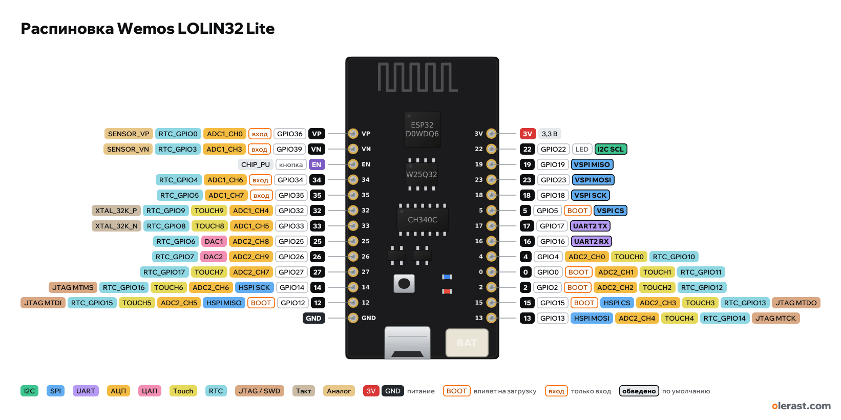
WEMOS LOLIN32 Lite, ESP32 (ESP32-D0WDQ6), 3.3 V logic, 25.4×50 mm, 26 pins
verified17.10.2026
- VPGPIO36inADC1_CH0RTC_GPIO0SENSOR_VP
- VNGPIO39inADC1_CH3RTC_GPIO3SENSOR_VN
- ENbuttonCHIP_PU
- 34GPIO34inADC1_CH6RTC_GPIO4
- 35GPIO35inADC1_CH7RTC_GPIO5
- 32GPIO32ADC1_CH4TOUCH9RTC_GPIO9XTAL_32K_P
- 33GPIO33ADC1_CH5TOUCH8RTC_GPIO8XTAL_32K_N
- 25GPIO25ADC2_CH8DAC1RTC_GPIO6
- 26GPIO26ADC2_CH9DAC2RTC_GPIO7
- 27GPIO27ADC2_CH7TOUCH7RTC_GPIO17
- 14GPIO14HSPI SCKADC2_CH6TOUCH6RTC_GPIO16JTAG MTMS
- 12GPIO12BOOTHSPI MISOADC2_CH5TOUCH5RTC_GPIO15JTAG MTDI
- GND
- 3V3.3 V
- 22GPIO22LEDI2C SCL
- 19GPIO19VSPI MISO
- 23GPIO23VSPI MOSI
- 18GPIO18VSPI SCK
- 5GPIO5BOOTVSPI CS
- 17GPIO17UART2 TX
- 16GPIO16UART2 RX
- 4GPIO4ADC2_CH0TOUCH0RTC_GPIO10
- 0GPIO0BOOTADC2_CH1TOUCH1RTC_GPIO11
- 2GPIO2BOOTADC2_CH2TOUCH2RTC_GPIO12
- 15GPIO15BOOTHSPI CSADC2_CH3TOUCH3RTC_GPIO13JTAG MTDO
- 13GPIO13HSPI MOSIADC2_CH4TOUCH4RTC_GPIO14JTAG MTCK
Top view, USB at the bottom, antenna at the top.
CompareDownload PNG- Chip
- ESP32 (ESP32-D0WDQ6)
- Logic
- 3.3 V
- Power
- Micro-USB 4.75-5.25 VLi-ion 3.7 V (PH-2.0 connector) 3.3-4.2 V3V 3-3.6 V
- Defaults in arduino-esp32 (board "LOLIN32 Lite")
- I2C: SDA 19, SCL 23SPI: MOSI 23, MISO 19, SCK 18, SS 5UART: TX 1, RX 3LED: 22
Which Wemos LOLIN32 Lite pins are safe to use
Free to use
GPIO4, GPIO13, GPIO14, GPIO16-19, GPIO23, GPIO25-27, GPIO32, GPIO33
Use with care
- GPIO0, GPIO2, GPIO5, GPIO12, GPIO15: strapping: the level at power-up selects the boot mode.
- GPIO22: onboard LED.
- GPIO34-36, GPIO39: input only, no output and no pull-ups.
Important
- 3.3 V logic, don't put 5 V on the GPIO.
- 34, 35, 36 (VP), 39 (VN) are input only, no pull-ups.
- ADC2 (GPIO0, 2, 4, 12–15, 25–27) doesn't work with Wi-Fi on. With Wi-Fi, use ADC1: 32–39.
- GPIO21 is not brought out to the header. In the "LOLIN32 Lite" core variant I2C is on 19 (SDA) and 23 (SCL), the same pins as MISO and MOSI: I2C and SPI do not work together by default, remap one of them.
- LED on GPIO22 (lights when LOW).
- Strapping pins on the header: 0, 2, 5, 12, 15. Keep GPIO12 low at power-up.
- Pins 16 and 17 are free (no PSRAM).
- Silkscreen labels are GPIO numbers (from photos), nets are from the Wemos schematic. Size and row positions are from photos, the board has no drawing.
- The header has no 5V and BAT pins: there is nothing to power external 5 V modules from.
- Battery connector polarity on clones is sometimes reversed: check before connecting.
Revisions and clones
- Clones with the same name: the battery connector may have reversed polarity and the regulator differs; the pin order is the same.
All pins
| Label | Number | Functions | Limits | Check |
|---|---|---|---|---|
| VP | GPIO36 | interruptADC1_CH0RTC_GPIO0SENSOR_VP | input onlynot 5 V tolerant | verifiedInput only: no output and no internal pull-ups. |
| VN | GPIO39 | interruptADC1_CH3RTC_GPIO3SENSOR_VN | input onlynot 5 V tolerant | verifiedInput only: no output and no internal pull-ups. |
| EN | CHIP_PU: enable and reset (low = reset) | onboard pull-uponboard button | verifiedThe RESET button on the board shorts it to ground. | |
| 34 | GPIO34 | interruptADC1_CH6RTC_GPIO4 | input onlynot 5 V tolerant | verifiedInput only: no output and no internal pull-ups. |
| 35 | GPIO35 | interruptADC1_CH7RTC_GPIO5 | input onlynot 5 V tolerant | verifiedInput only: no output and no internal pull-ups. |
| 32 | GPIO32 | interruptPWM (LEDC)ADC1_CH4TOUCH9RTC_GPIO9XTAL_32K_P (32 kHz crystal) | not 5 V tolerant | verified |
| 33 | GPIO33 | interruptPWM (LEDC)ADC1_CH5TOUCH8RTC_GPIO8XTAL_32K_N (32 kHz crystal) | not 5 V tolerant | verified |
| 25 | GPIO25 | interruptPWM (LEDC)ADC2_CH8RTC_GPIO6DAC1 | ADC2 doesn't work with Wi-Fi onnot 5 V tolerant | verifiedADC2: while Wi-Fi is running, analogRead on this pin doesn't work. For ADC with Wi-Fi, use ADC1 (GPIO32–39). |
| 26 | GPIO26 | interruptPWM (LEDC)ADC2_CH9RTC_GPIO7DAC2 | ADC2 doesn't work with Wi-Fi onnot 5 V tolerant | verifiedADC2: while Wi-Fi is running, analogRead on this pin doesn't work. For ADC with Wi-Fi, use ADC1 (GPIO32–39). |
| 27 | GPIO27 | interruptPWM (LEDC)ADC2_CH7TOUCH7RTC_GPIO17 | ADC2 doesn't work with Wi-Fi onnot 5 V tolerant | verifiedADC2: while Wi-Fi is running, analogRead on this pin doesn't work. For ADC with Wi-Fi, use ADC1 (GPIO32–39). |
| 14 | GPIO14 | interruptPWM (LEDC)ADC2_CH6TOUCH6RTC_GPIO16HSPI SCKJTAG MTMS | ADC2 doesn't work with Wi-Fi onnot 5 V tolerant | verifiedADC2: while Wi-Fi is running, analogRead on this pin doesn't work. For ADC with Wi-Fi, use ADC1 (GPIO32–39). |
| 12 | GPIO12 | interruptPWM (LEDC)ADC2_CH5TOUCH5RTC_GPIO15HSPI MISOJTAG MTDI | affects boot (strapping)ADC2 doesn't work with Wi-Fi onnot 5 V tolerant | verifiedMTDI: selects the flash voltage at reset. High = 1.8 V, so a module with 3.3 V flash won't boot. Internal pull-down.ADC2: while Wi-Fi is running, analogRead on this pin doesn't work. For ADC with Wi-Fi, use ADC1 (GPIO32–39). |
| GND | Ground | verified | ||
| 3V | 3.3 V | power inputpower output | verifiedME6211 regulator output (500 mA) or 3.3 V input. | |
| 22 | GPIO22 | interruptPWM (LEDC)I2C SCL | not 5 V tolerantonboard LED | verifiedThe blue LED is tied to 3.3 V through 2 kΩ on the board: it lights when LOW. LED_BUILTIN = 22. |
| 19 | GPIO19 | interruptPWM (LEDC)VSPI MISO | not 5 V tolerant | verified |
| 23 | GPIO23 | interruptPWM (LEDC)VSPI MOSI | not 5 V tolerant | verified |
| 18 | GPIO18 | interruptPWM (LEDC)VSPI SCK | not 5 V tolerant | verified |
| 5 | GPIO5 | interruptPWM (LEDC)VSPI CS (SS) | affects boot (strapping)not 5 V tolerant | verifiedStrapping: SDIO slave timing. Internal pull-up, don't pull it low during reset. |
| 17 | GPIO17 | interruptPWM (LEDC)UART2 TX | not 5 V tolerant | verified |
| 16 | GPIO16 | interruptPWM (LEDC)UART2 RX | not 5 V tolerant | verified |
| 4 | GPIO4 | interruptPWM (LEDC)ADC2_CH0TOUCH0RTC_GPIO10 | ADC2 doesn't work with Wi-Fi onnot 5 V tolerant | verifiedADC2: while Wi-Fi is running, analogRead on this pin doesn't work. For ADC with Wi-Fi, use ADC1 (GPIO32–39). |
| 0 | GPIO0 | interruptPWM (LEDC)ADC2_CH1TOUCH1RTC_GPIO11 | affects boot (strapping)ADC2 doesn't work with Wi-Fi onnot 5 V tolerant | verifiedAt reset: low = firmware download mode (BOOT button). Internal pull-up.ADC2: while Wi-Fi is running, analogRead on this pin doesn't work. For ADC with Wi-Fi, use ADC1 (GPIO32–39).Auto-flashing through the DTR/RTS of the CH340C bridge toggles this pin. There is no BOOT button on the board. |
| 2 | GPIO2 | interruptPWM (LEDC)ADC2_CH2TOUCH2RTC_GPIO12 | affects boot (strapping)ADC2 doesn't work with Wi-Fi onnot 5 V tolerant | verifiedAt reset it must be low or floating for download mode. Internal pull-down.ADC2: while Wi-Fi is running, analogRead on this pin doesn't work. For ADC with Wi-Fi, use ADC1 (GPIO32–39). |
| 15 | GPIO15 | interruptPWM (LEDC)ADC2_CH3TOUCH3RTC_GPIO13HSPI CSJTAG MTDO | affects boot (strapping)ADC2 doesn't work with Wi-Fi onnot 5 V tolerant | verifiedMTDO: low at reset silences the bootloader log on UART0. Internal pull-up.ADC2: while Wi-Fi is running, analogRead on this pin doesn't work. For ADC with Wi-Fi, use ADC1 (GPIO32–39). |
| 13 | GPIO13 | interruptPWM (LEDC)ADC2_CH4TOUCH4RTC_GPIO14HSPI MOSIJTAG MTCK | ADC2 doesn't work with Wi-Fi onnot 5 V tolerant | verifiedADC2: while Wi-Fi is running, analogRead on this pin doesn't work. For ADC with Wi-Fi, use ADC1 (GPIO32–39). |
Sources
Every pin is verified against the manufacturer's documents.
- WEMOS LOLIN32 Lite V1.0.0 schematic (LOLIN32_Lite.sch, 2017-08-30; Wemos removed the board from its site, copy at done.land)schematic, checked 17.10.2026nets JP1 and JP2 (13 + 13): VP, VN, CHIP_PU, 34, 35, 32, 33, 25, 26, 27, 14, 12, GND; 3V3, 22, 19, 23, 18, 5, 17, 16, 4, 0, 2, 15, 13; bare ESP32-D0WDQ6 chip, W25Q32 flash, CH340C, ME6211, TP4054, LED on IO22 to 3V3
- Zephyr: Wemos Lolin32 Litethird-party source, checked 17.10.2026LED on GPIO22, CH340C, TP4054, PH-2 connector
- arduino-esp32: variants/lolin32-lite/pins_arduino.hArduino core, checked 17.10.2026LED_BUILTIN 22, TX 1, RX 3, SDA 19, SCL 23, SS 5, MOSI 23, MISO 19, SCK 18
- ESP32 Series Datasheet (Espressif)datasheet, checked 15.10.2026IO MUX and pin functions, ADC1/ADC2, touch, DAC, RTC GPIO, strapping (GPIO0, 2, 5, 12, 15), flash pins GPIO6–11, input-only GPIO34–39
- ESP-IDF: GPIO & RTC GPIO (ESP32)user guide, checked 15.10.2026GPIO6–11 used by flash, GPIO34–39 input only with no pull-ups, strapping pins, GPIO1/3 UART0
- ESP-IDF: ADC Oneshot Mode Driver (ESP32)user guide, checked 15.10.2026ADC2 can't be used while Wi-Fi is running
- arduino-esp32: variants/esp32/pins_arduino.hArduino core, checked 15.10.2026defaults: TX 1, RX 3, SDA 21, SCL 22, SS 5, MOSI 23, MISO 19, SCK 18
Size: no drawing, from photos and measurements ±0.5 mm; rows 0.9 inch apart (approximate).
FAQ
- Which Wemos LOLIN32 Lite pins are I2C, SPI and UART?
- By default in arduino-esp32 (board "LOLIN32 Lite"): I2C: SDA GPIO19, SCL GPIO23; SPI: MOSI GPIO23, MISO GPIO19, SCK GPIO18, SS GPIO5; UART: TX GPIO1, RX GPIO3.
- Which pin is the Wemos LOLIN32 Lite LED on?
- Blue LED on GPIO22 (lights when LOW).
- Are the Wemos LOLIN32 Lite pins 5 V tolerant?
- No. The logic is 3.3 V and the pins are not 5 V tolerant: use a divider or a level shifter for 5 V signals.
- Does ADC2 on the Wemos LOLIN32 Lite work with Wi-Fi on?
- No. ADC2 pins (GPIO0, GPIO2, GPIO4, GPIO12-15, GPIO25-27) can't read analog while Wi-Fi is on. With Wi-Fi, use GPIO32-36, GPIO39 for the ADC.
You might also need
Similar boards
Next
- Emotion keychainmy ESP32 project, prototype
- ESP32 music playermy ESP32 project, prototype
- DITHR//CAMmy ESP32 project, prototype
Need firmware or a device built on ESP32? I'll build it to order