BMS 2S protection board pinout
BMS 2S protection board (7.4 V, with balancing), 2S protection controller (HY2120/HY2213 and equivalents) + MOSFET, 7.4 V logic, 46×18 mm, 5 pins
partly verified17.10.2026
Top view, cell taps on the left, load on the right.
BuyDownload PNG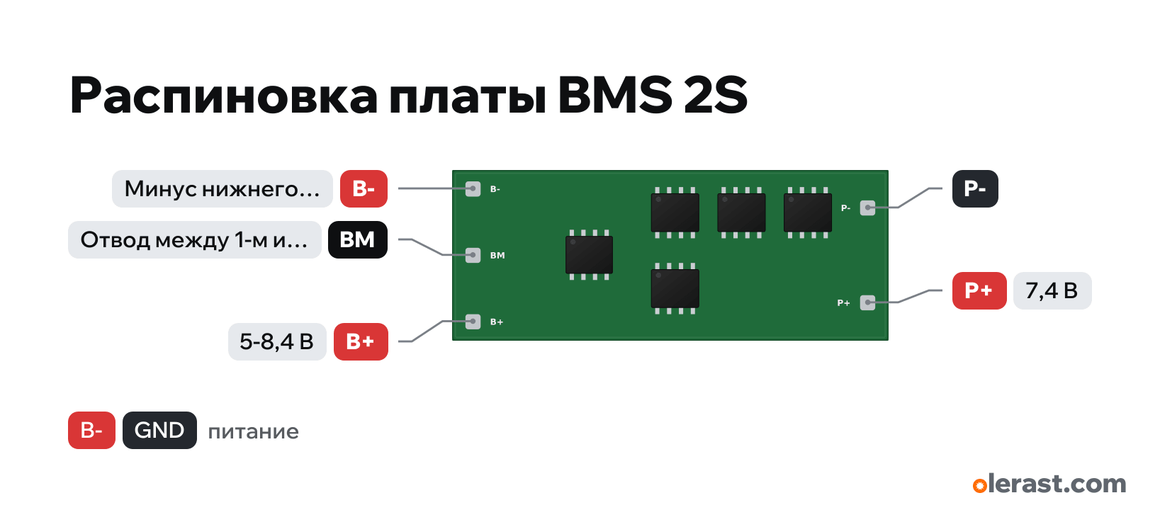
- Chip
- 2S protection controller (HY2120/HY2213 and equivalents) + MOSFET
- Logic
- 7.4 V
- Power
- B+ 5-8.4 V
Important
- Connect the taps in order from the negative: B−, BM, B+. Before connecting, check the voltage of each tap with a multimeter.
- The circuit's common ground is P−, not B−: if you take ground from B−, over-discharge and overcurrent protection won't work.
- Without balancing (cheap boards do not have it or it is tens of mA) the cells drift apart: charge with a 2S 8.4 V charger and check each cell from time to time.
- The board's current rating (3 A, 10 A, 20 A) is printed on the board or in the listing: choose one with margin over the motors' inrush current.
- Charge at P+ and P− with 8.4 V (a 2S charger), the load goes to the same pins.
Revisions and clones
- Boards with separate P− (charging) and C− (load): they have three load pins.
All pins
| Label | Number | Functions | Limits | Check |
|---|---|---|---|---|
| B- | Negative of the lower cell (through switches to P−) | not verifiedProtection board with no manufacturer: the B−, B+, P−, P+ labels are standard (DW01/HY2120), the pad layout differs between boards. Read the labels on your board.Battery negative. Not the common ground: protection switches sit between B− and P−.Labelled on other revisions as: B−, BAT- | ||
| BM | Tap between the 1st and 2nd cell (balancing, monitoring) | not verifiedProtection board with no manufacturer: the B−, B+, P−, P+ labels are standard (DW01/HY2120), the pad layout differs between boards. Read the labels on your board.Positive of the 1st cell from the bottom (3.7 V from B−). Almost no current flows: thin wire.Labelled on other revisions as: B1, MB | ||
| B+ | 7.4 V | power input | not verifiedProtection board with no manufacturer: the B−, B+, P−, P+ labels are standard (DW01/HY2120), the pad layout differs between boards. Read the labels on your board.Pack positive: 6.0-8.4 V.Labelled on other revisions as: BAT+ | |
| P- | Ground | not verifiedProtection board with no manufacturer: the B−, B+, P−, P+ labels are standard (DW01/HY2120), the pad layout differs between boards. Read the labels on your board.Load and charging negative: this is the circuit's common ground. The protection opens it.Labelled on other revisions as: P−, OUT- | ||
| P+ | 7.4 V | power output | not verifiedProtection board with no manufacturer: the B−, B+, P−, P+ labels are standard (DW01/HY2120), the pad layout differs between boards. Read the labels on your board.Load and charging positive: connected directly to B+ (some boards have no P+ pad, take the positive from B+).Labelled on other revisions as: OUT+ |
Sources
Not verified against the manufacturer: 5 of 5 pins. The pin card says what confirms each one and where sources disagree.
- ShillehTek: 1S 3.7V 3A 2MOS BMS Li-ion 18650 protection board manualthird-party source, checked 17.10.20261S: B+, B−, P+, P−; DW01 and 2 MOSFETs; load and charger on P+ and P−
- done.land: 2S 10A Battery Management Systemsthird-party source, checked 17.10.20262S: B−, BM (midpoint, sometimes B1), B+, P−, P+; charge 8.4–9.0 V on P+ and P−
- Cirkit Designer: 3S BMSthird-party source, checked 17.10.20263S: B−, B1, B2, B+, P−, P+; connect the taps from negative to positive
Size: not dimensioned: protection boards come in different shapes (approximate).
You might also need
Similar boards
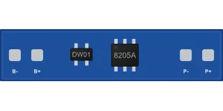
BMS 1S protection board (3.7 V, DW01 + 8205A)
DW01A + FS8205A4 pins
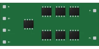
BMS 3S protection board (11.1 V, with balancing)
3S protection controller (HY2120/HY2213 and equivalents) + MOSFET6 pins
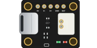
Adafruit Micro-Lipo USB-C LiPo charger (MCP73831, product 4410)
MCP73831T-2ACI/OT7 pins
IP5306 power bank module (2 A charging + 5 V 2 A output, USB-C and USB-A)
IP53065 pins